Vehicle sliding door device, and vehicle provided with vehicle sliding door device

Inactive Publication Date: 2016-10-06
MITSUBISHI HEAVY IND LTD
View PDF10 Cites 1 Cited by
  • Summary
  • Abstract
  • Description
  • Claims
  • Application Information

AI Technical Summary

Benefits of technology

[0020]In the vehicle sliding door device, and the vehicle provided with the vehicle sliding door device, it is possible to

Problems solved by technology

Wind pressure during traveling of the vehicle or vibration of the vehicle may cause vibra

Method used


Image

  • Vehicle sliding door device, and vehicle provided with vehicle sliding door device
  • Vehicle sliding door device, and vehicle provided with vehicle sliding door device
  • Vehicle sliding door device, and vehicle provided with vehicle sliding door device

Examples


first embodiment

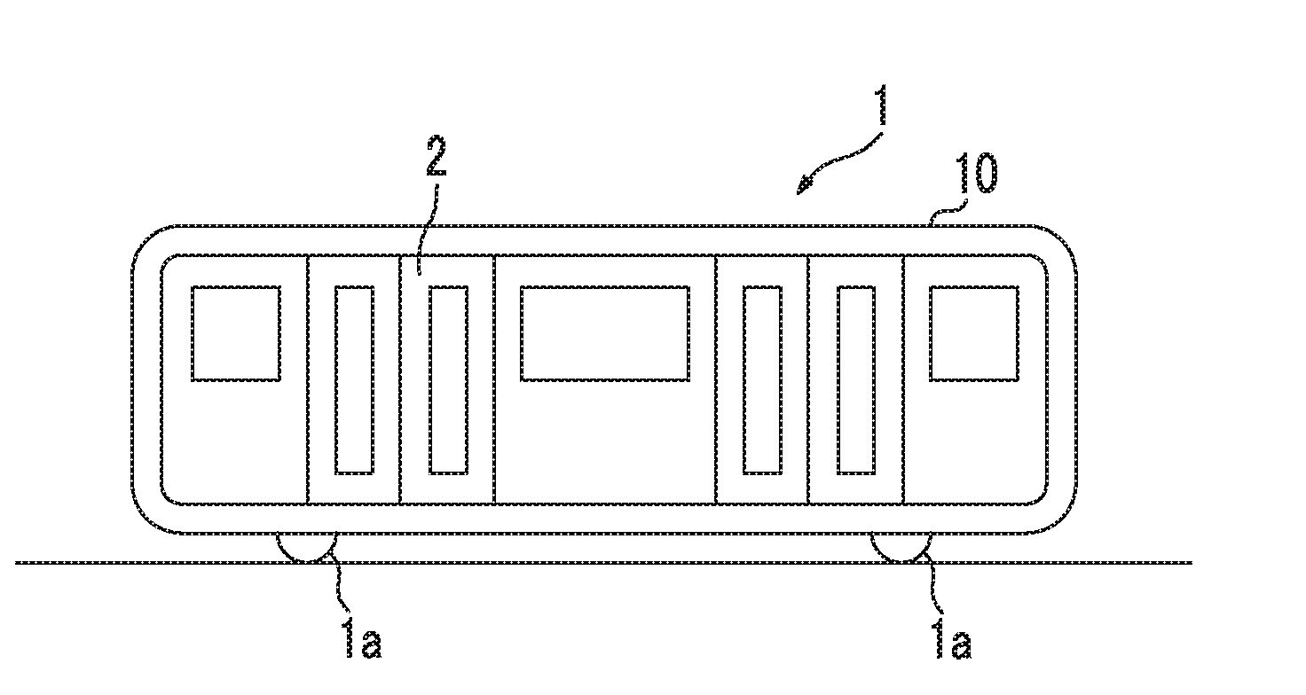
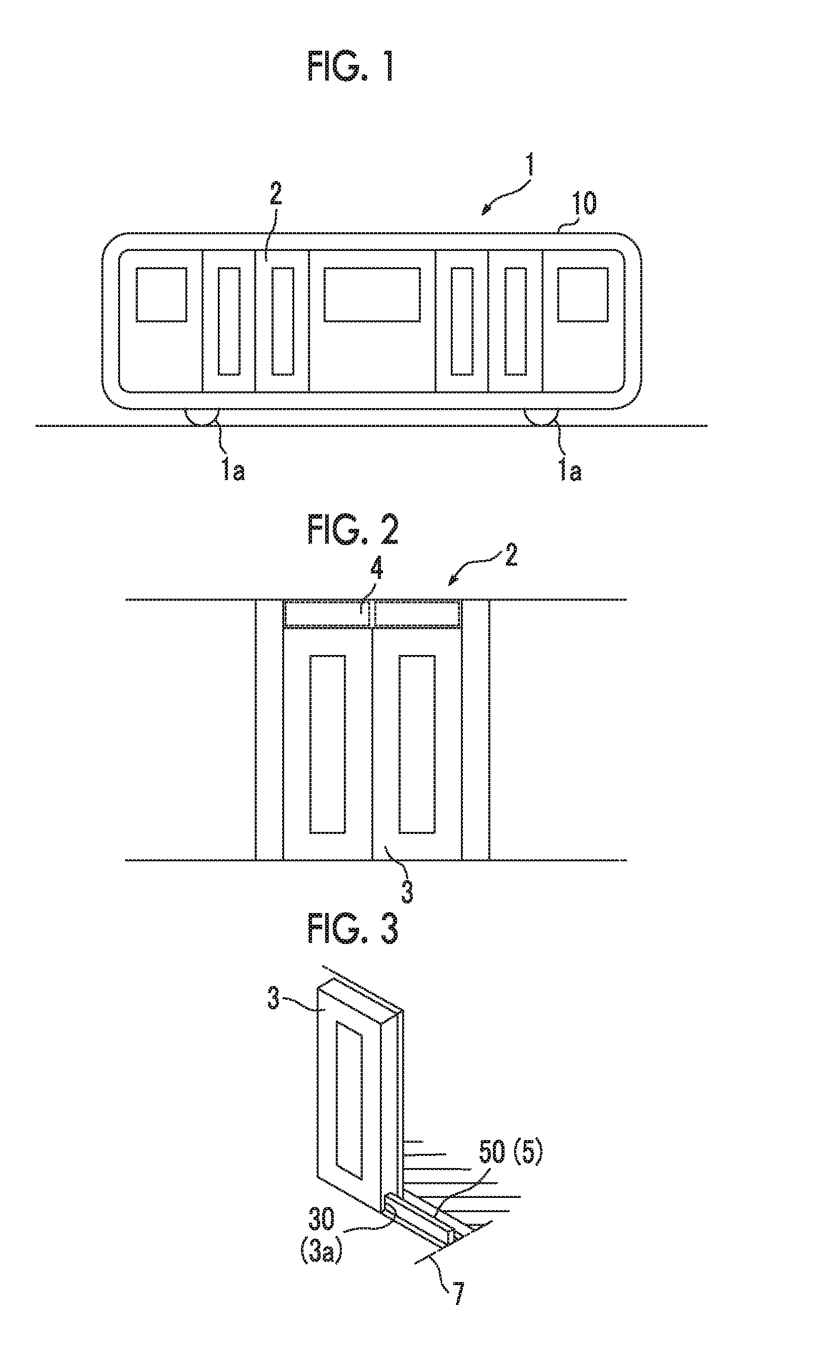
[0033]A vehicle 1 and a sliding door device 2 in a first embodiment of the present invention will be described with reference to FIGS. 1 to 5.

[0034]As illustrated in FIG. 1, the vehicle 1 in the embodiment includes a vehicle body 10 accommodating transportation targets (for example, passengers) thereinside; a sliding door device 2; and a traveling device 1a traveling the vehicle body 10.

[0035]An inner space is formed inside the vehicle body 10, and accommodates the transportation targets. Seats (not illustrated) or straps (not illustrated) are provided in the inner space, and are used by passengers which are transportation targets. A motor or an internal combustion engine is used as the traveling device 1a.

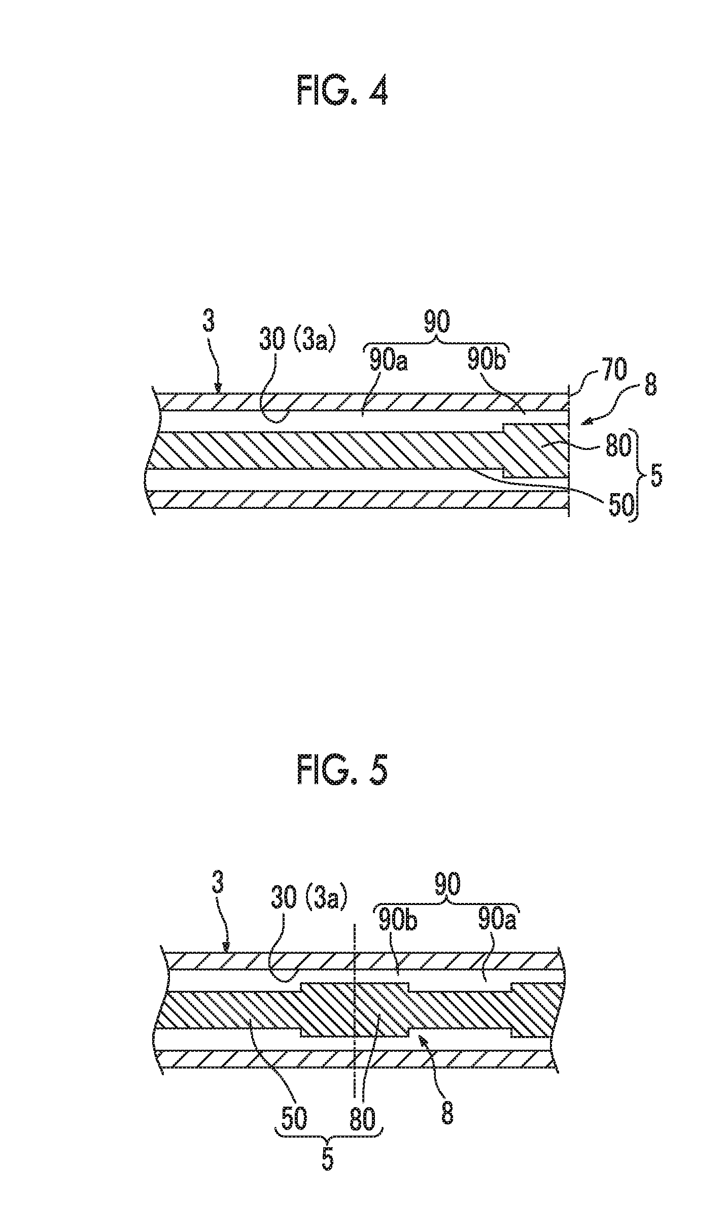
[0036]As illustrated in FIGS. 2 to 4, the sliding door device 2 in the embodiment is provided on a side surface of the vehicle body 10, and opens and closes an opening portion of the side surface which is an entrance. The sliding door device 2 includes a sliding door rail 5; a sl...

second embodiment

[0045]The vehicle 1 and the sliding door device 2 in a second embodiment of the present invention will be described with reference to FIGS. 7A and 7B.

[0046]The shape of the rattling prevention unit 8 in the second embodiment is different from that of the rattling prevention unit 8 in the first embodiment.

[0047]As illustrated in FIGS. 7A and 7B, the rattling prevention unit 8 in the embodiment is formed in such a way that a gap between the engagement unit 3a of the sliding door 3 and the sliding door rail 5 in the width direction of the sliding door rail 5 is gradually decreased from the regions other than the region of the end portion 70 of the sliding door rail 5 to the region of the end portion 70. More specifically, the rattling prevention unit 8 is formed of an enlarged portion 83 or 84, both sides of which protrude in such a way as to be gradually increased in the width direction of the sliding door rail 5 from the regions other than the region of the end portion 70 of the slid...

third embodiment

[0049]The vehicle 1 and the sliding door device 2 in a third embodiment of the present invention will be described with reference to FIG. 8.

[0050]The third embodiment is different from the first embodiment in that the rattling prevention unit 8 is formed of an enlarged portion 85, both sides of which are differently formed in the width direction of the sliding door rail 5.

[0051]As illustrated in FIG. 8, the enlarged portion 85 is formed as the rattling prevention unit 8 in the embodiment in the region of the end portion 70 of the sliding door rail 5, and includes a first enlarged portion 85a and a second enlarged portion 85b which are respectively formed on the both sides in the width direction of the sliding door rail 5. The first enlarged portion 85a and the second enlarged portion 85b are formed in such a way that positions in the movement direction, in which decreasing of a gap 95 between the engagement unit 3a of the sliding door 3 and the sliding door rail 5 is started, are di...


PUM


Abstract

Disclosed is a vehicle sliding door device including a sliding door rail formed along a movement direction, and a sliding door including an engagement unit engaged with the sliding door rail, and which is opened and closed when the engagement unit is moved along the sliding door rail. The sliding door rail includes a rattling prevention unit in the region of an end section corresponding to the closed position of the sliding door, in which a gap between the engagement unit of the sliding door and the sliding door rail is narrower than a gap between the engagement unit of the sliding door and the sliding door rail in other regions.

Description

RELATED APPLICATIONS[0001]The present application is a National Phase entry of International Application No. PCT / JP2014 / 068574, filed Jul. 11, 2014, which claims priority of Japanese Application No. 2013-235901, filed Nov. 14, 2013.TECHNICAL FIELD[0002]The present invention relates to a vehicle sliding door device and a vehicle provided with a vehicle sliding device.BACKGROUND ART[0003]A vehicle such as an electric train includes a vehicle sliding door device configured to include a sliding door rail at an entrance of the vehicle, and a sliding door that is moved along the sliding door rail. The vehicle sliding door device opens and closes the entrance of the vehicle by moving the sliding door along the sliding door rail.[0004]Wind pressure during traveling of the vehicle or vibration of the vehicle may cause vibration of the sliding door of such a vehicle sliding door device, and thus, noise may occur. For example, PTL 1 discloses a device in which sliding door holding members are ...

Claims


Application Information

Patent Timeline
IPC IPC(8): E05D15/06B61D19/00B61D1/00E05F15/00
CPCE05D15/06E05F15/00E05Y2900/531B61D1/00B61D19/005E05F7/04E05D15/0621
Inventor JOREN, ICHIRO
Owner MITSUBISHI HEAVY IND LTD
Why Eureka
Try Eureka