Device, method, and non-transitory computer-readable medium for identifying body part imaged by endoscope

Active Publication Date: 2016-10-06
FUJIFILM CORP
View PDF3 Cites 5 Cited by
  • Summary
  • Abstract
  • Description
  • Claims
  • Application Information

AI Technical Summary

Benefits of technology

[0025]According to the aspects of the present invention, the a

Problems solved by technology

However, it is difficult to distinguish the body part (e.g. a gastrointestinal tract) being subjected to the endoscopic examination, through visual observation of the image displayed on the monitor, so that the imaged body part may not be identified correctly.
However, the method for identifying the imaged body part based on the insertion amount, the bend amount, and the rotation amount as described in the Japanese patent No. 4262741 and the US2015/0208947 has low accuracy in identifying the imaged body part.
In case where the direction of the pati

Method used


Image

  • Device, method, and non-transitory computer-readable medium for identifying body part imaged by endoscope
  • Device, method, and non-transitory computer-readable medium for identifying body part imaged by endoscope
  • Device, method, and non-transitory computer-readable medium for identifying body part imaged by endoscope

Examples


first embodiment

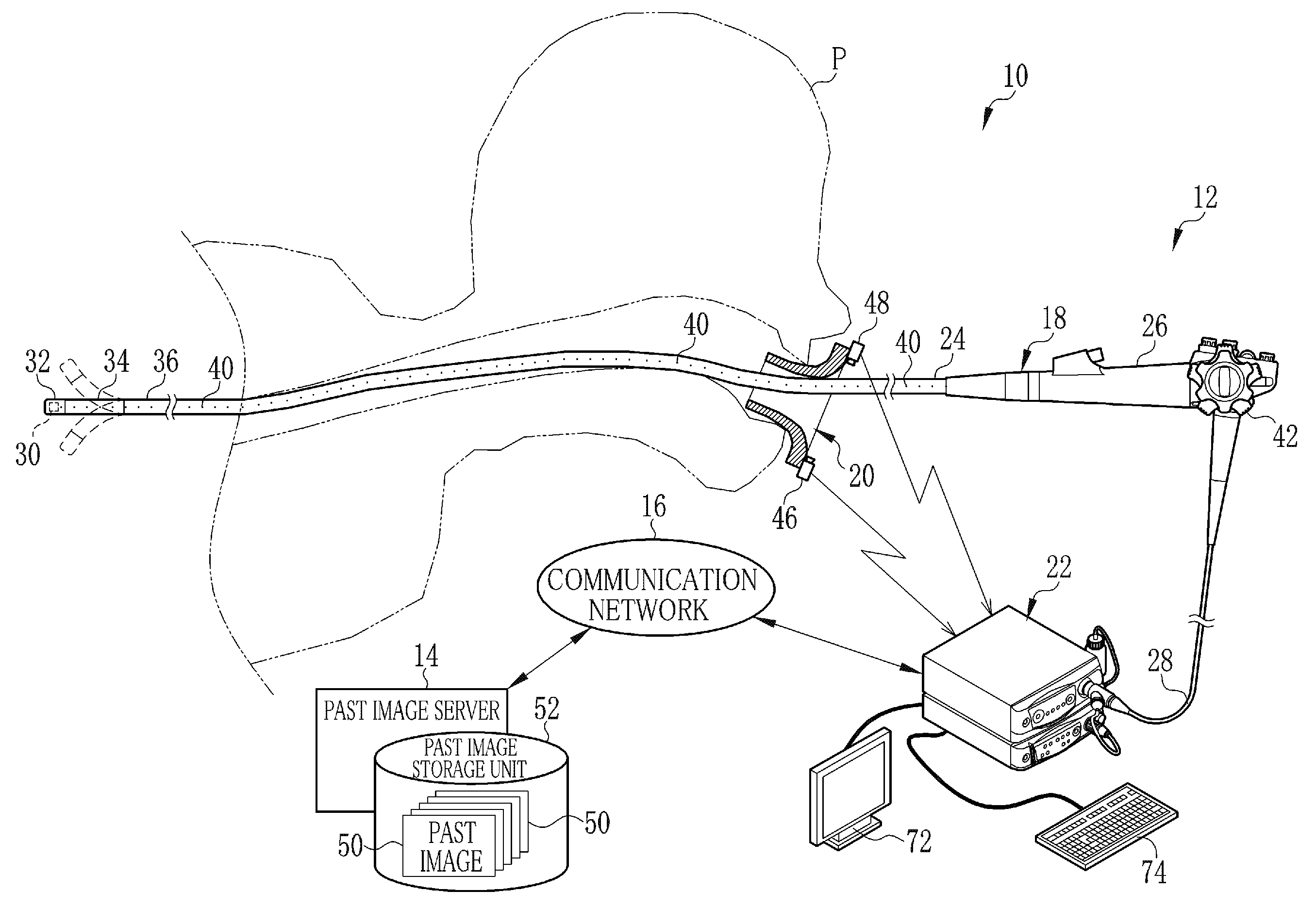
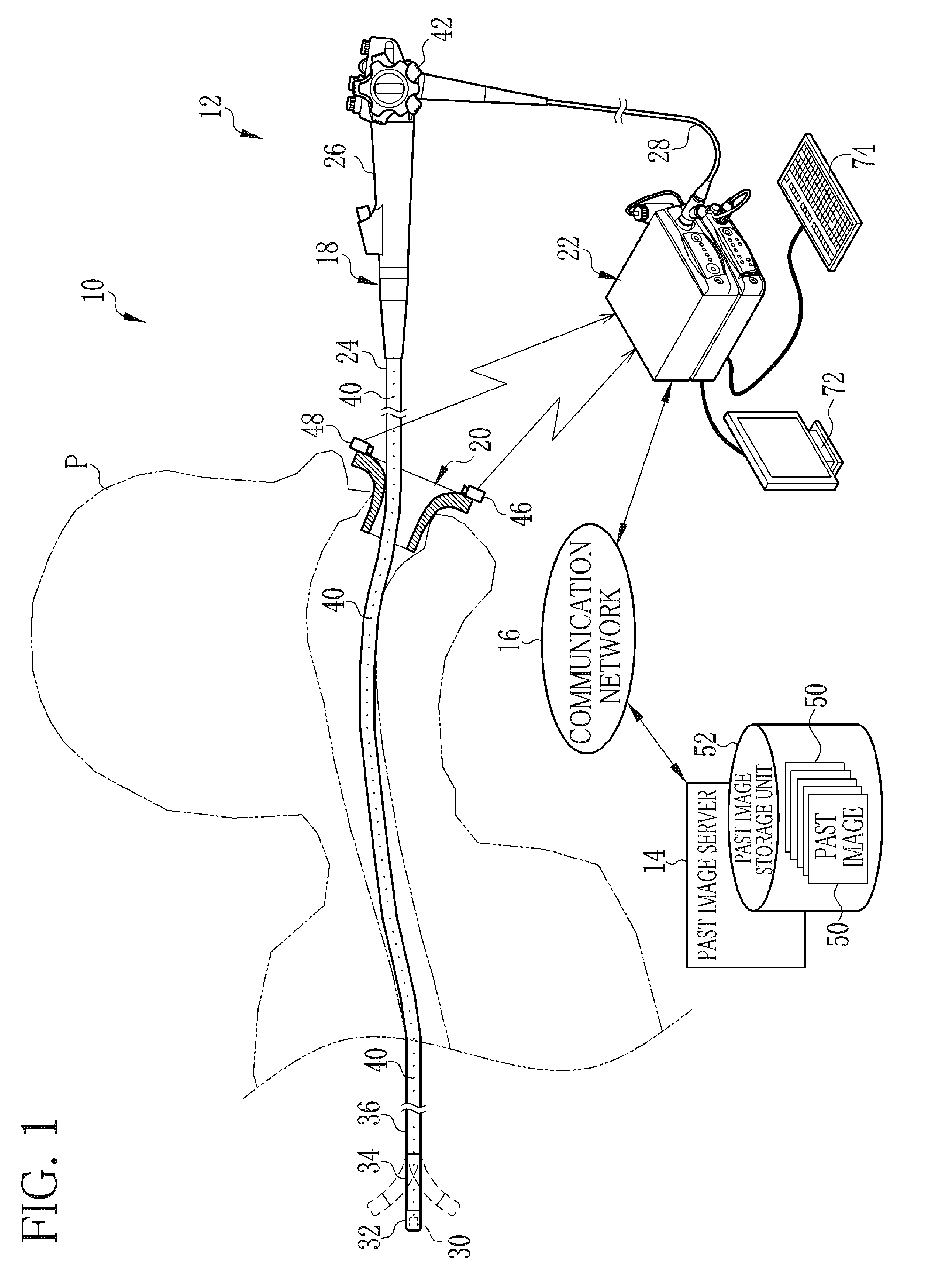
[0039]As illustrated in FIG. 1, an endoscope system 10 comprises an endoscope apparatus 12 and a past image server 14, which are interconnected through a communication network 16 such as the Internet or a LAN (Local Area Network). The endoscope apparatus 12 comprises an endoscope 18, a mouthpiece 20, a processor device 22, a display 72, and a keyboard 74. The processor device 22 is an example of a body part identification device.

[0040]The endoscope 18 comprises an insertion section 24, which is to be inserted into a body cavity of a patient, and an operation unit 26 provided at a proximal end of the insertion section 24. the endoscope 18 is connected to the processor device 22 through a cord 28. The insertion section 24 comprises a distal portion 32, a flexible portion 34, and a flexible tube 36. The distal portion 32 incorporates an imaging unit 30. The flexible portion 34 bends to change a direction of the distal portion 32 (that is, an imaging direction of the imaging unit 30). T...

second embodiment

[0099]In the above embodiment, the current image 49 and the past image 50 of the same patient (the same patient of interest) are used for the comparison. Instead, the past image 50 of a patient (another patient) different from the patient of interest may be used to identify the imaged body part.

[0100]The comparison between the current image 49 and the past image 50 of different patients results in similarity lower than that in the comparison between the current image 49 and the past image 50 of the same patient (the same patient of interest) even if the imaged body part is the same. However, in a case where the past image server 14 does not contain the past image 50 of the same patient as in the current image 49, the current image 49 cannot be compared with the past image 50 of the same patient. In this case, it is effective to use the past image 50 of another patient for the comparison with the current image 49 of the patient of interest.

[0101]As illustrated in FIG. 9, it is prefer...

third embodiment

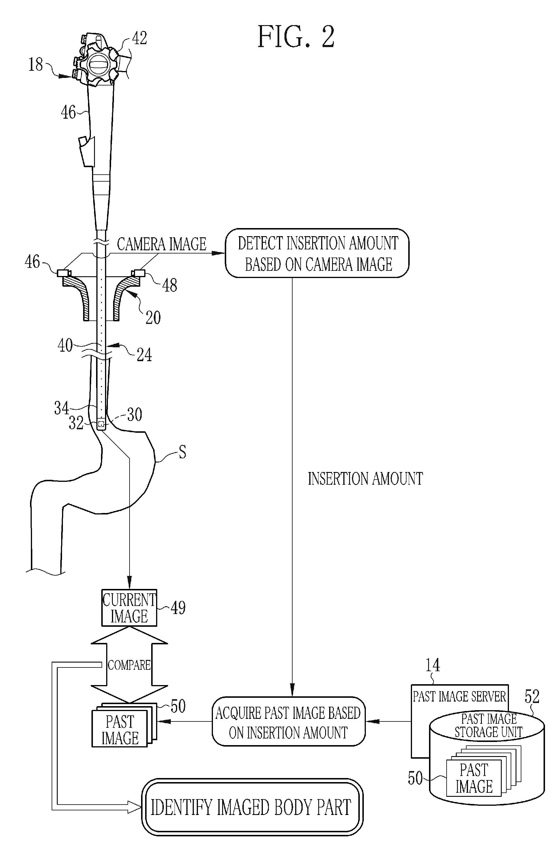
[0102]An example of a third embodiment illustrated in FIG. 10 uses a correspondence table 111, which stores the correspondence between the insertion amounts and the candidates for the imaged body part. In the first embodiment, the insertion amount itself is used as a search condition (search keyword) to retrieve the past image 50. In the third embodiment, first, the past image acquisition unit 92 refers to the correspondence table 111, to determine the candidates for the imaged body part based on the detected insertion amount. The past image acquisition unit 92 designates the candidates for the imaged body part as the search condition, to acquire the past images 50 corresponding to the candidates for the imaged body part from the past image storage unit 52.

[0103]There is a certain correspondence between the insertion amount and the imaged body part. The correspondence table 111 stores the correspondence between the range of the insertion amount and the candidate for the imaged body ...


PUM


Abstract

In an endoscope system, an insertion amount of an insertion unit is detected based on camera images captured by two cameras provided to a mouthpiece. Then, past images of a predetermined range corresponding to the detected insertion amount are acquired from a past image storage unit. A current image is compared with each of the acquired past images to calculate similarity between the current image and each of the past images. A body part captured in the past image having the highest similarity with the current image is determined to be the body part captured in the current image.

Description

CROSS-REFERENCE TO RELATED APPLICATIONS[0001]The present application claims priority under 35 U.S.C. §119 to Japanese Patent Application No. 2015-070156, filed Mar. 30, 2015. Each of the above applications is hereby expressly incorporated by reference, in its entirety, into the present application.BACKGROUND OF THE INVENTION[0002]1. Field of the Invention[0003]The present invention relates to a device, a method, and a non-transitory computer-readable medium for identifying a body part imaged by an imaging unit provided at a distal end of an insertion section of an endoscope.[0004]2. Description Related to the Prior Art[0005]Endoscopes for capturing images of a patient's body cavity are widely known. An insertion section, which incorporates an imaging unit at its distal end, of the endoscope is inserted into the patient's body cavity and the image is captured by the imaging unit. The captured image is displayed on a monitor in real time. A doctor observes an imaged body part through ...

Claims


Application Information

Patent Timeline
IPC IPC(8): G06K9/00G06K9/62A61B1/00A61B1/273A61B5/06A61B1/05G06T7/00H04N5/225
CPCG06K9/00362G06T7/0044G06K9/00671G06K9/6215H04N2005/2255A61B1/273A61B5/066A61B1/05A61B1/0002H04N5/225G06T7/0016G06T2207/10068G06T2207/30092A61B5/064A61B1/0005A61B1/00154A61B1/01A61B2034/2065G06T7/74A61B1/000094A61B1/009H04N23/555H04N23/63
Inventor MIURA, NOBUYUKI
Owner FUJIFILM CORP
Why Eureka
Try Eureka