Power converter and power conditioner

a technology of power converter and power conditioner, which is applied in the direction of power conversion system, dc-dc conversion, instruments, etc., can solve the problem of relative large loss as the whole of the power converter, and achieve the effect of enhancing conversion efficiency and reducing loss

Active Publication Date: 2016-10-06
PANASONIC INTELLECTUAL PROPERTY MANAGEMENT CO LTD
View PDF3 Cites 17 Cited by
  • Summary
  • Abstract
  • Description
  • Claims
  • Application Information

AI Technical Summary

Benefits of technology

[0024]According to the configuration of the invention, because a voltage to be applied to the first conversion circuit is boosted by the third conversion circuit, a voltage to be applied to the transformer becomes high even when a range of a voltage to be applied to

Problems solved by technology

In other words, a relatively-large current flows through an input side of the boosting circuit 301, an

Method used


Image

  • Power converter and power conditioner
  • Power converter and power conditioner
  • Power converter and power conditioner

Examples


embodiment 1

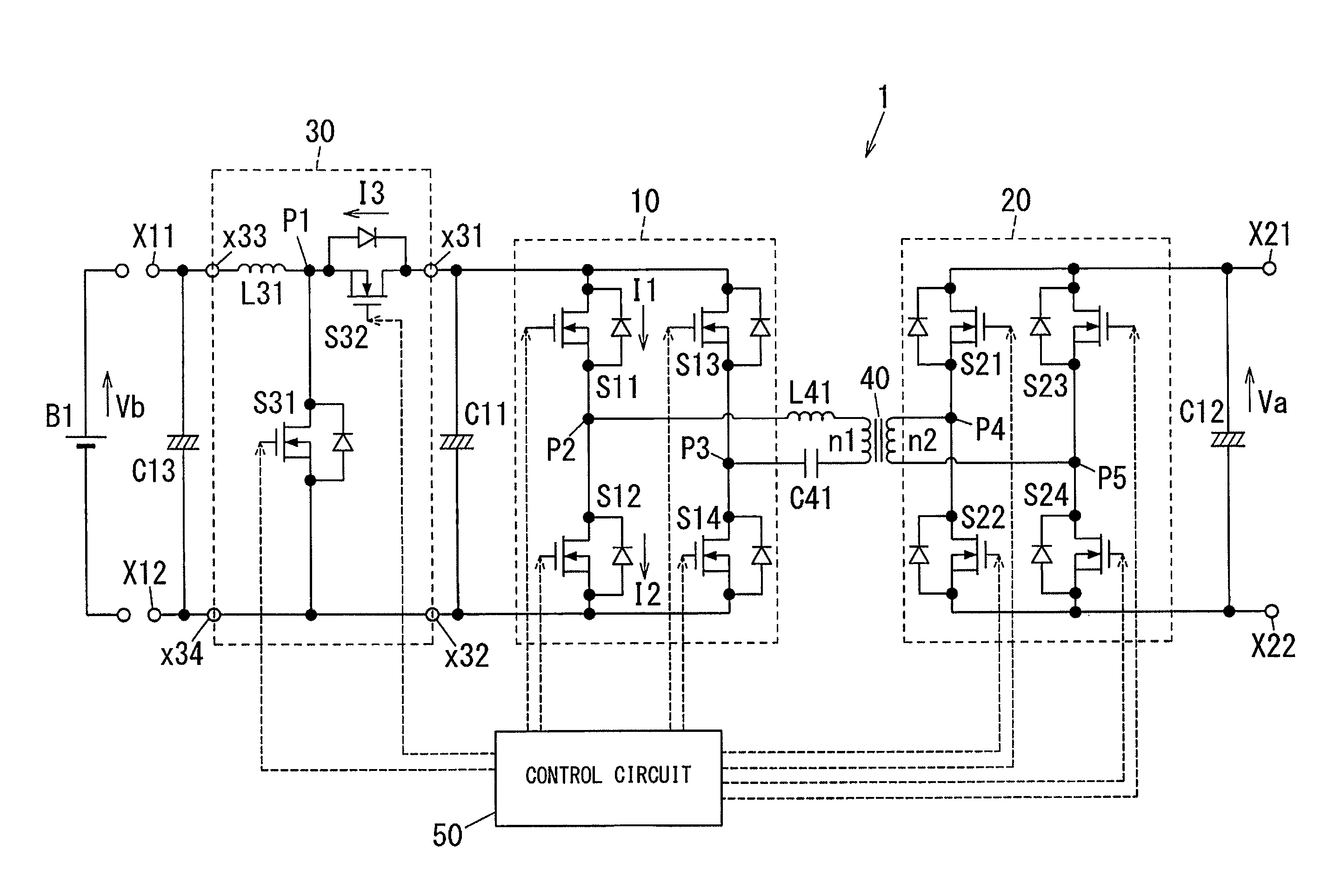
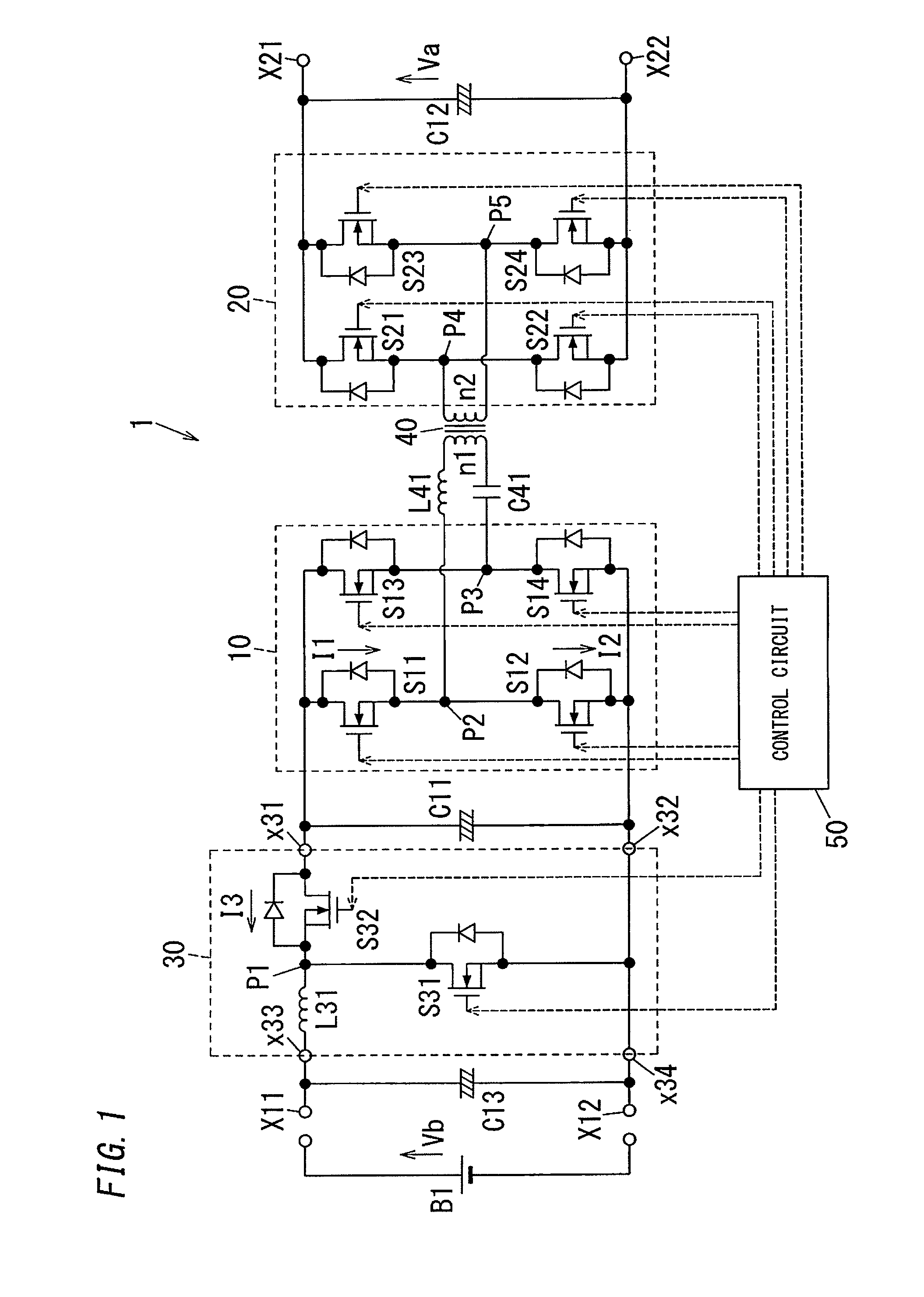
[0038]As shown in FIG. 1, a power converter 1 of the present embodiment includes a first conversion circuit 10 and a second conversion circuit 20 that are configured to perform electric power conversion. Between the first and second conversion circuits 10 and 20, a transformer 40 is connected. Each of the first and second conversion circuits 10 and 20 is configured to transfer electric power via the transformer 40. The power converter 1 further includes a third conversion circuit 30 connected with connection terminals of the first conversion circuit 10 on a DC side thereof.

[0039]Each of the first and second conversion circuits 10 and 20 is configured to perform bidirectional DC / AC power conversion. In other words, the first and second conversion circuits 10 and 20 and the transformer 40 constitute a conversion circuit that is configured to perform bidirectional DC / DC power conversion as the whole.

[0040]The third conversion circuit 30 is a circuit provided at a pre-stage of the first...

embodiment 2

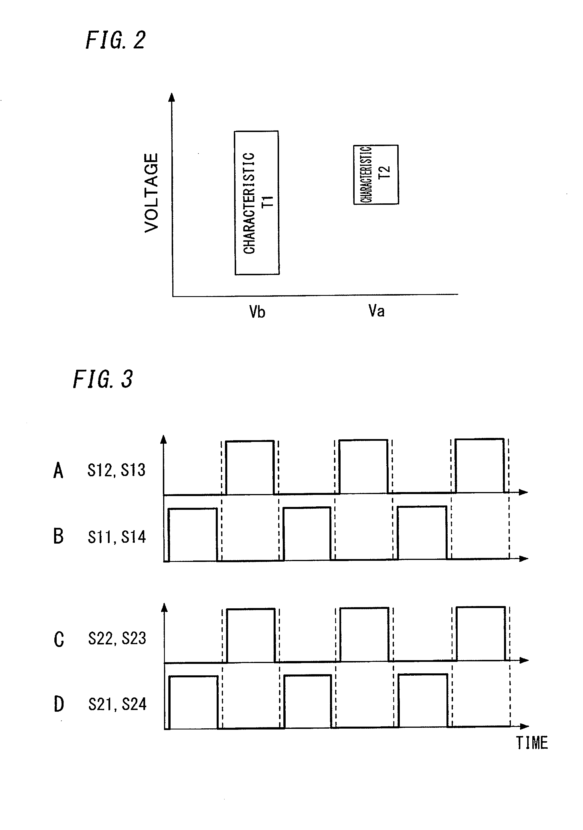
[0106]The operation described in Embodiment 1 makes the cycle of the on / off of the switch elements S11 to S14 and S21 to S24 of the first and second conversion circuits 10 and 20 be different from the cycle of the on / off of the switch element S32 of the third conversion circuit 30. The operation prevents unbalance between currents that flow through the switch elements S11 to S14 and S21 to S24 provided in the first and second conversion circuits 10 and 20. In order to achieve the same aim, a third conversion circuit 30A of the present embodiment has a configuration shown in FIG. 9.

[0107]In other words, the third conversion circuit 30A of the present embodiment has a configuration in which two circuits are connected in parallel, and each of the two circuits has the same configuration as that of the third conversion circuit 30 of Embodiment 1 shown in FIG. 1. One of the two circuits connected in parallel includes: two switch elements S31 and S32 connected in series; and an inductor L3...


PUM


Abstract

A power converter 1 includes a first conversion circuit 10 connected with a first winding n1 of a transformer 40, and a second conversion circuit 20 connected with a second winding n2 of the transformer 40. The first and second conversion circuits 10 and 20 are configured to perform bidirectional power conversion. The power converter further includes a third conversion circuit 30 that is a circuit provided at a pre-stage of the first conversion circuit 10 in a direction of transferring electric power toward the second conversion circuit 20 from the first conversion circuit 10. The third conversion circuit 30 is configured to perform bidirectional power conversion, and function as a boosting chopper circuit upon transferring electric power toward the second conversion circuit 20 from the first conversion circuit 10.

Description

TECHNICAL FIELD[0001]The invention relates generally to power converters and power conditioners, and, more particularly, to a power converter that includes a transformer between two conversion circuits for performing power conversion, and a power conditioner using the power converter.BACKGROUND ART[0002]Conventionally, there has been known a power converter that includes a transformer between two conversion circuits for performing power conversion, as a kind of power converter that performs bidirectional DC / DC conversion, or performs bidirectional DC / AC conversion (e.g., refer to JP 2009-177940 A (hereinafter, referred to as“Document 1”)).[0003]As shown in FIG. 12, the power converter in Document 1 includes a transformer 401 between a primary-side DC / AC conversion part 101 and a secondary-side DC / AC conversion part 201. In addition, the power converter has a configuration that a boosting circuit 301 is connected with the secondary-side DC / AC conversion part 201. This power converter...

Claims


Application Information

Patent Timeline
IPC IPC(8): H02M3/335H02M1/08
CPCH02M3/33507H02M2001/0009H02M1/08H02M3/1582H02M3/33584H02M1/007H02M1/0009
Inventor TAMURA, HIDEKIKIDERA, KAZUNORIYOSHIZAWA, JIN
Owner PANASONIC INTELLECTUAL PROPERTY MANAGEMENT CO LTD
Why Eureka
Try Eureka