Assist handle for car

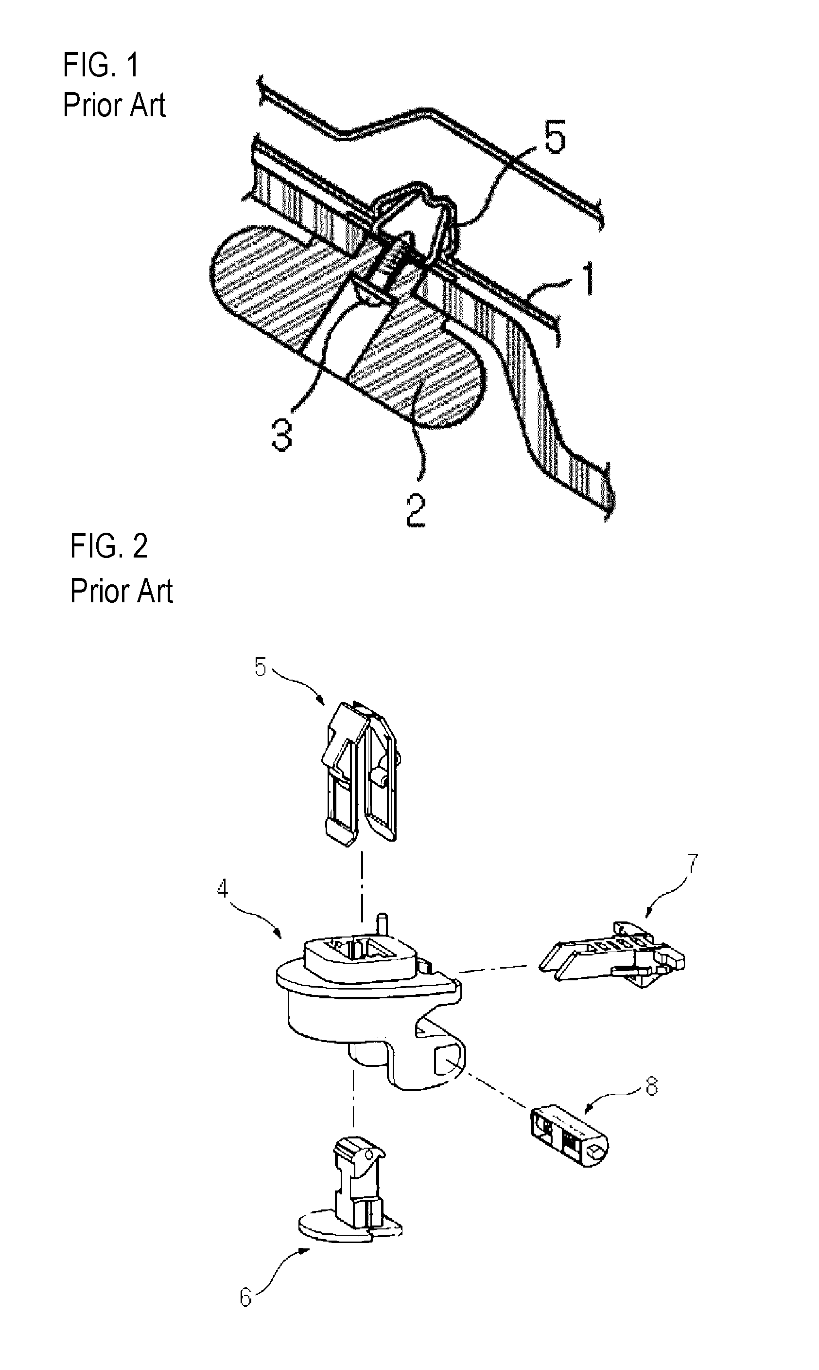
a technology for fixing clips and handles, applied in the direction of vehicle components, superstructure subunits, vehicle arrangements, etc., can solve the problems of deteriorating productivity, easy decoupling, change or repair of fixing clips, etc., to improve the performance of the fixing clip, improve the appearance, and improve the effect of the effect of the effect of the effect of the fixing clip

Inactive Publication Date: 2016-10-13
NIFCO KOREA
View PDF3 Cites 6 Cited by
  • Summary
  • Abstract
  • Description
  • Claims
  • Application Information

AI Technical Summary

Benefits of technology

[0022]According to the present invention in the above configuration, the assist handle is mounted by the fixing means on the body panel of a vehicle but the hinge parts for the rotation of the handle is not exposed, thereby improving the appearance.
[0023]Further, the damper and the return spring are provided to the assist handle such that the returning of the assist handle is smoothly carried out, thereby improving the performance thereof.
[0024]In addition, the number of the parts of the fixing means is reduced, thereby promoting the cost reduction and the simplification of the assembling work while securing the simple separation of the parts in the case of change or repair.

Problems solved by technology

However, the prior art assist handle has disadvantages that the mounting of the assist handle to the body panel takes too much time, deteriorating productivity, and the fixing clip once mounted is not easily decoupled so that the change or repair of the fixing clip is difficult so far.
However, the above prior art technique still has a problem that the elasticity of the return spring is excessively transmitted in the process of returning the assist handle such that the returning speed of the assist handle is too fast or a part thereof collides with the inside surface of the vehicle, generating noise.
Further, the mounting module is formed of a plurality of separate parts, causing the difficulties in the maintenance thereof together with the increase in the cost of materials and the assembling work.

Method used


Image

  • Assist handle for car
  • Assist handle for car
  • Assist handle for car

Examples


Embodiment Construction

[0032]Hereinafter, embodiments of the present invention will now be described with respect to the configuration in detail with reference to the drawings.

[0033]An assist handle for a car according to the present invention is derived to be mounted by own fixing means but without using any additional coupling members and to prevent the exposure of the hinge parts thereof so as to improve the appearance thereof.

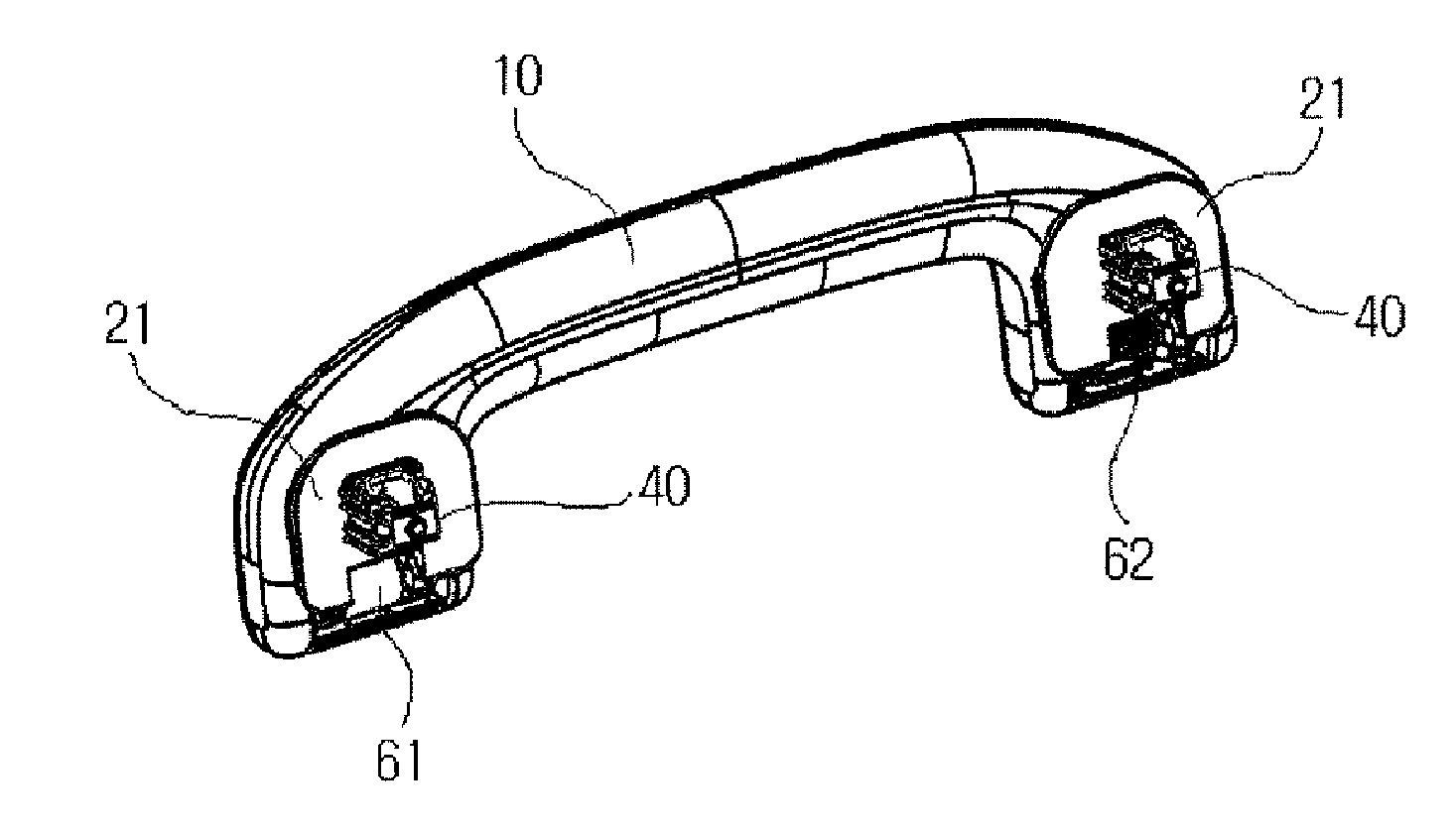
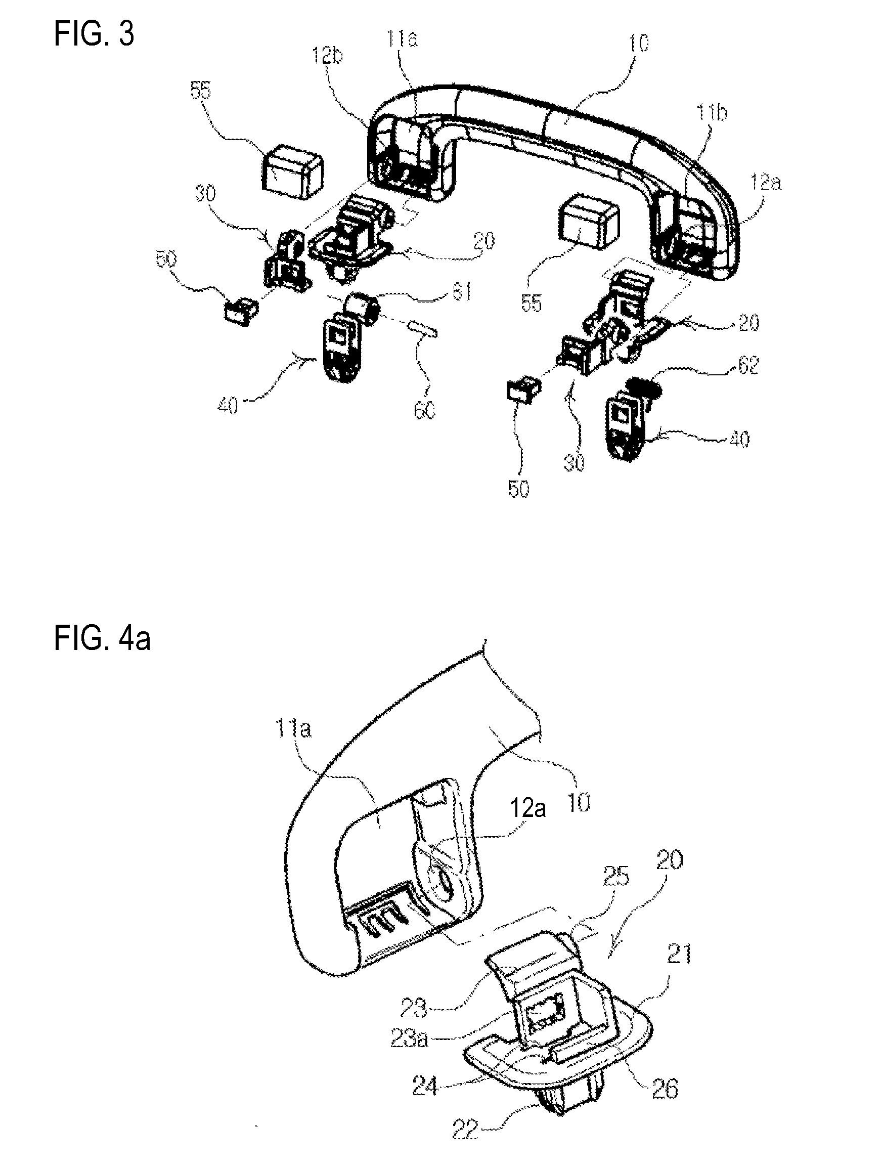
[0034]Referring to FIG. 3 to FIG. 5, an assist handle 10 mounted on the body panel of a car has mounting spaces 11a, 11b formed at both end portions of the handle, wherein fixing means are coupled to the mounting spaces 11a, 11b such that the fixing means prevent the exposure of hinge parts for the rotating the assist handle 10 and fixing clips 40 composing the fixing means are formed to be simply mounted on the body panel.

[0035]To this end, the fixing means mainly includes main brackets 20 and auxiliary brackets 30 which are provided to the assist handle 10, fixing clips 40 coup...


PUM


Abstract

An assist handle for a car includes an assist handle having mounting spaces and hinge grooves; main brackets positioned in the mounting spaces of the assist handle and having fitting protrusions, clip insertion holes and hinge shafts fitted into the hinge grooves on one side of the mounting spaces; auxiliary brackets having coupling plates provided with hook fixing holes overlapping front portions of body portions of the main brackets and hinge shafts fitted into the hinge grooves on another side of the mounting spaces; fixing clips adapted to couple to the body panel of the car at one side and inserted into the clip insertion holes at the other side such that holding pieces are placed at the same positions as the hook fixing holes; and hooks fitted into the holding pieces and the hook fixing holes to fix the fixing clips, the main brackets and the auxiliary brackets.

Description

TECHNICAL FIELD[0001]The present invention relates to an assist handle for a car, wherein the assist handle can be mounted by own fixing means without using any additional coupling members, and hinge parts thereof are prevented from being exposed so as to improve the appearance of the assist handle.BACKGROUND ART[0002]In general, an assist handle for a car denotes an auxiliary handle which is provided to a head liner in the proximity of the door of a passenger's seat such that a passenger can use the same for maintaining his balance. Referring to FIG. 1, an assist handle according to a prior art has a body panel 1 coupled to a fixing clip 5 having elasticity and an assist handle 2 fixed to the fixing clip 5 by means of a tapping screw 3.[0003]However, the prior art assist handle has disadvantages that the mounting of the assist handle to the body panel takes too much time, deteriorating productivity, and the fixing clip once mounted is not easily decoupled so that the change or repa...

Claims


Application Information

Patent Timeline
Patent Type & Authority Applications(United States)
IPC IPC(8): B60N3/02
CPCB60N3/026B60N3/02B62D25/06
Inventor YANG, HYO KEUNHONG, CHANG SUN
Owner NIFCO KOREA
Why Eureka
Try Eureka