Shoe and pedal system for bicycles

a pedal system and bicycle technology, applied in the direction of footwear, vehicle cranks, vehicle components, etc., can solve the problems of one or more feet inadvertently falling off the pedal, injury to the rider's leg, loss of control of the bicycle, etc., to achieve comfortable and easy detachment of the shoe from the pedal

Inactive Publication Date: 2016-10-20
KLEIN DESIGNS LLC
View PDF9 Cites 26 Cited by
  • Summary
  • Abstract
  • Description
  • Claims
  • Application Information

AI Technical Summary

Benefits of technology

[0013]There is provided a hybrid bicycle pedal which combines certain characteristics of a conventional “clip-in” bicycle pedal and a standard flat pedal to attain benefits associated with each type of pedal. In particular, the pedal system allows riders to engage the sole of their shoe with the pedal to feel an operative engagement therebetween during normal riding conditions, while allowing the rider to easily detach the shoe from the pedal should the need arise. The shoe may also be configured to allow the user to comfortably and easily wear the shoe for other non-bicycle activities, such as walking and running. Thus, the pedal system allows a user to seamlessly transition between bicycling and walking / running.

Problems solved by technology

Although platform pedals may be sufficient for leisurely bicycle riding, more aggressive styles of bicycle riding may result in one or more of the rider's feet inadvertently slipping off of the pedal.
Such slippage may result in the rider losing control of the bicycle, or cause injury to the rider's leg if the rider attempts to re-engage with the pedal while the bicycle is moving.
Although the strap aides in preventing the rider's shoe from slipping off the pedal, the strap also suffers from many deficiencies.
Another deficiency associated with the strap is that the strap may only be configured to engage with the rider's foot when the foot is placed on one side of the pedal.
However, the cage may only loosely retain the foot, and thus, slippage may still occur.
Furthermore, the cage may be adapted for use on one side of the pedal, which may create difficulties in engaging with the cage when the bicycle is in motion, as the cage has a tendency to hang from the underside of the pedal.
The clip-in pedal system may suffer from certain disadvantages making use of such pedal system undesirable.
For instance, the complexity associated with engaging and disengaging the shoe from the pedal may result in the clip-in pedal system being unfavorable when the rider repeatedly engages and releases the shoe from the pedal (e.g., to balance the bicycle, etc.).
Furthermore, engagement between the shoe and pedal may be difficult if the shoe or pedal become clogged with dirt or mud.
Another significant drawback associated with conventional clip-in pedal systems pertains to the shoes.
In other words, such clip-in pedal shoes are not intended for conventional shoe use.
In this regard, it may be difficult or uncomfortable to walk in the shoes because of the hard, rigid cleat extending from the bottom of the shoe.
Moreover, the cleat may damage soft surfaces, like hardwood floors

Method used


Image

  • Shoe and pedal system for bicycles
  • Shoe and pedal system for bicycles
  • Shoe and pedal system for bicycles

Examples


Embodiment Construction

[0031]The detailed description set forth below in connection with the appended drawings is intended as a description of certain embodiments of a bicycle pedal system and is not intended to represent the only forms that may be developed or utilized. The description sets forth the various structure and / or functions in connection with the illustrated embodiments, but it is to be understood, however, that the same or equivalent structure and / or functions may be accomplished by different embodiments that are also intended to be encompassed within the scope of the present disclosure. It is further understood that the use of relational terms such as first and second, and the like are used solely to distinguish one entity from another without necessarily requiring or implying any actual such relationship or order between such entities.

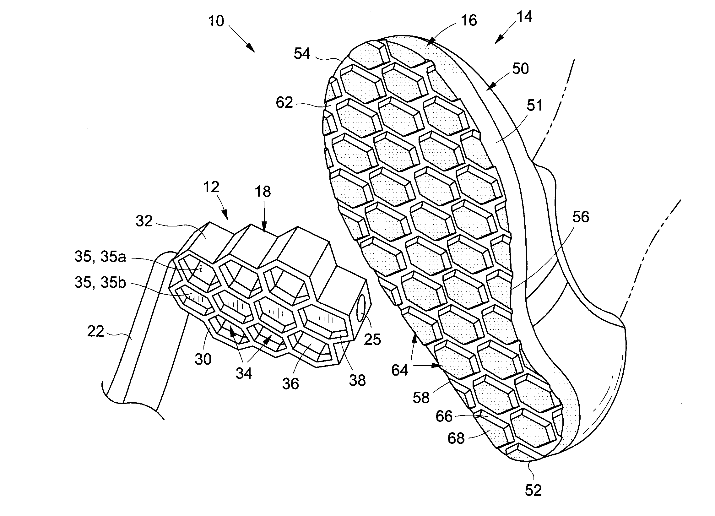
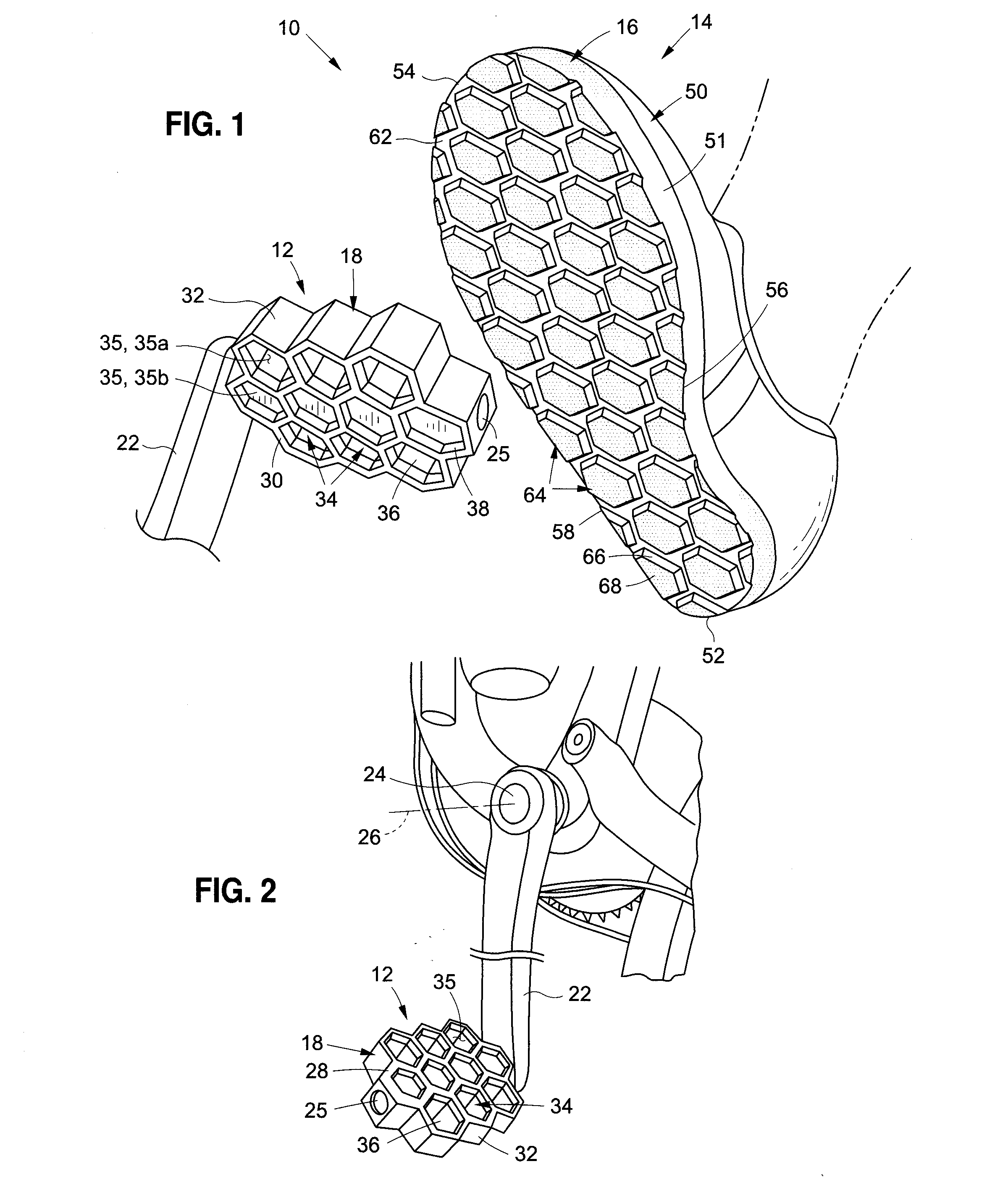
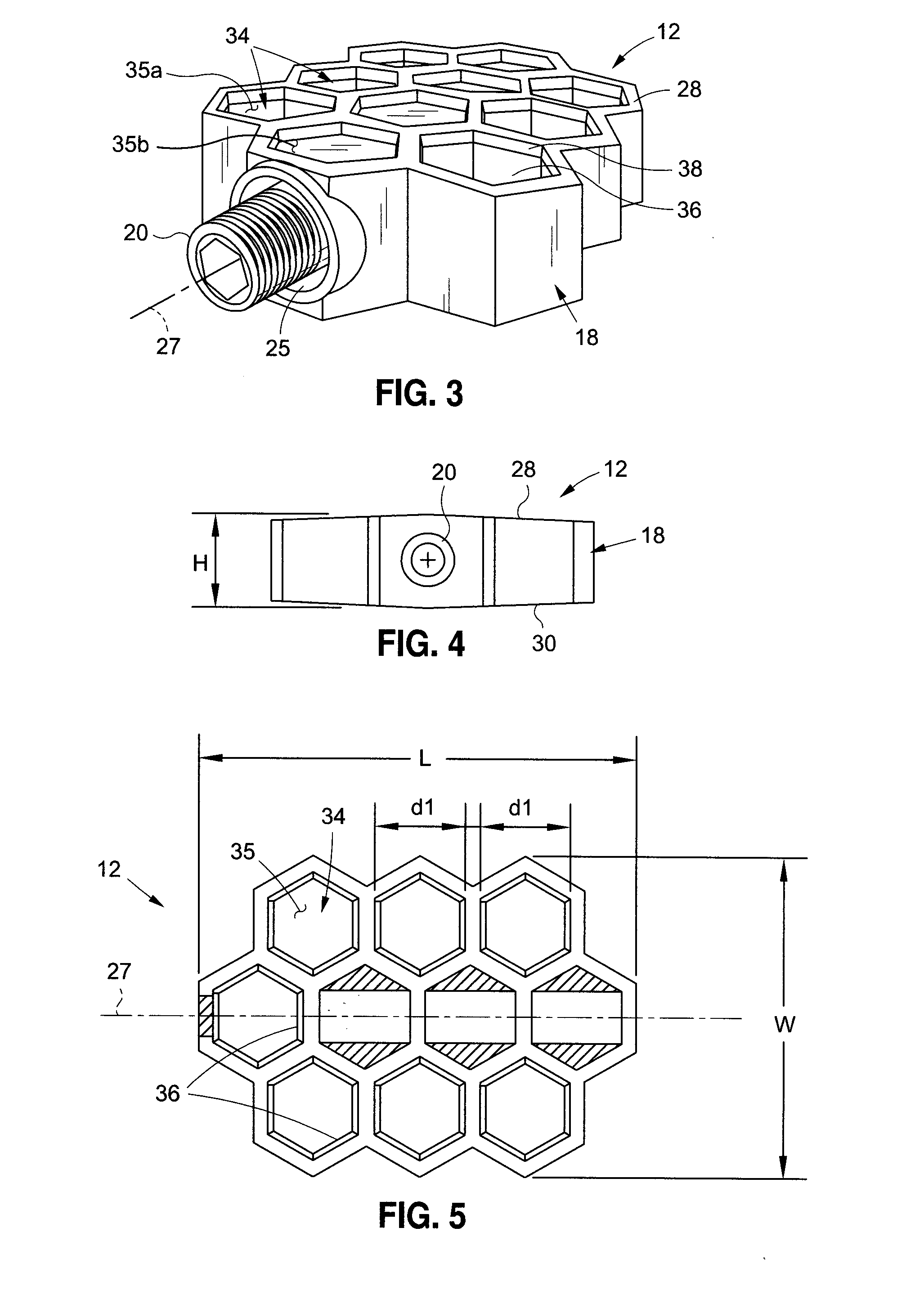
[0032]Various aspects of the present disclosure are directed toward a system 10 including a uniquely configured bicycle pedal 12 and a shoe 14 having a sole 1...


PUM


Abstract

A bicycle pedal system which allows riders to engage the sole of their shoe with the pedal to feel an operative engagement therebetween during normal riding conditions, while allowing the rider to easily detach the shoe from the pedal should the need arise. The system includes a shoe sole wearable on the foot of a user, wherein the shoe sole includes a lower surface and a plurality of first engagement elements extending from the lower surface. The system further comprises a bicycle pedal including a first surface, an opposing second surface, and a plurality of second engagement elements extending from the first surface and being complimentary to the first engagement elements. The shoe sole is configured to be selectively engageable with the pedal, with the first engagement elements being registered with the second engagement elements when the shoe sole is engaged with the pedal.

Description

CROSS-REFERENCE TO RELATED APPLICATIONS[0001]Not ApplicableSTATEMENT RE: FEDERALLY SPONSORED RESEARCH / DEVELOPMENT[0002]Not ApplicableBACKGROUND OF THE INVENTION[0003]1. Field of the Invention[0004]The present invention relates generally to a pedaling system for a bicycle, and more specifically, to a bicycle pedal and a corresponding shoe configured to have cooperating engagement elements which allow a portion of the shoe to be selectively registered with the bicycle pedal when operating a bicycle to prevent slip-off of the shoe from the pedal.[0005]2. Description of the Related Art[0006]Bicycles are typically propelled by a rider, with the rider's feet being operatively engaged with respective pedals to transfer energy from the rider's legs to the bicycle. In particular, the pedals are operatively coupled to at least one of the wheels through an intervening gear and chain system for converting the pedaling motion of the rider's legs to rotation of the bicycle wheels. Accordingly, ma...

Claims


Application Information

Patent Timeline
Patent Type & Authority Applications(United States)
IPC IPC(8): B62M3/08A43B5/14A43B13/22
CPCB62M3/086A43B5/14A43B13/223
Inventor KLEIN, MAXWELL C.REDDING, JOHN
Owner KLEIN DESIGNS LLC
Why Eureka
Try Eureka