Concealing lavatory supply storage caddy

a technology for storage caddy and lavatory, which is applied in the direction of auxiliary device closure, internal fitting, auxiliary device closure, etc., can solve the problems of unsightly plunger merely residing on the lavatory floor, not easy to be easily accessible when needed, and not aesthetically pleasing nor sanitary placement of exposed toilet plungers in bathrooms

Inactive Publication Date: 2016-10-27
GORMELEY ERIC J
View PDF3 Cites 7 Cited by
  • Summary
  • Abstract
  • Description
  • Claims
  • Application Information

AI Technical Summary

Problems solved by technology

Placement of an exposed toilet plunger in a bathroom is not aesthetically pleasing nor sanitary.
On the other hand, when a toilet plunger is stored in an out of sight location, it may not be easily accessible when needed.
Therefore, it is desirable to have a toilet plunger close at hand in a bathroom, preferably within a caddy or container as a plunger merely residing on a lavatory floor is unsightly.
For example, many containers are often unattractive in appearance, and may not blend in with the overall décor or aesthetics of the bathroom.
This may be inconvenient to the user and unsanitary.
Another problem may be that the toilet plunger may inadvertently become dislodged from the container during transport.
Still further, in bathrooms where space is at a premium, there may not be sufficient space to store a plunger as well as other toilet necessities within a reasonable perimeter of the toilet bowl.
Another common problem encountered in bathrooms is the limited amount of space.
Thus, storage of lavatory necessities can oftentimes be difficult.
While certain toiletries are small and unassuming in terms of space, extra rolls of toilet paper are unsightly and take up a great deal of space.

Method used


Image

  • Concealing lavatory supply storage caddy
  • Concealing lavatory supply storage caddy
  • Concealing lavatory supply storage caddy

Examples


Embodiment Construction

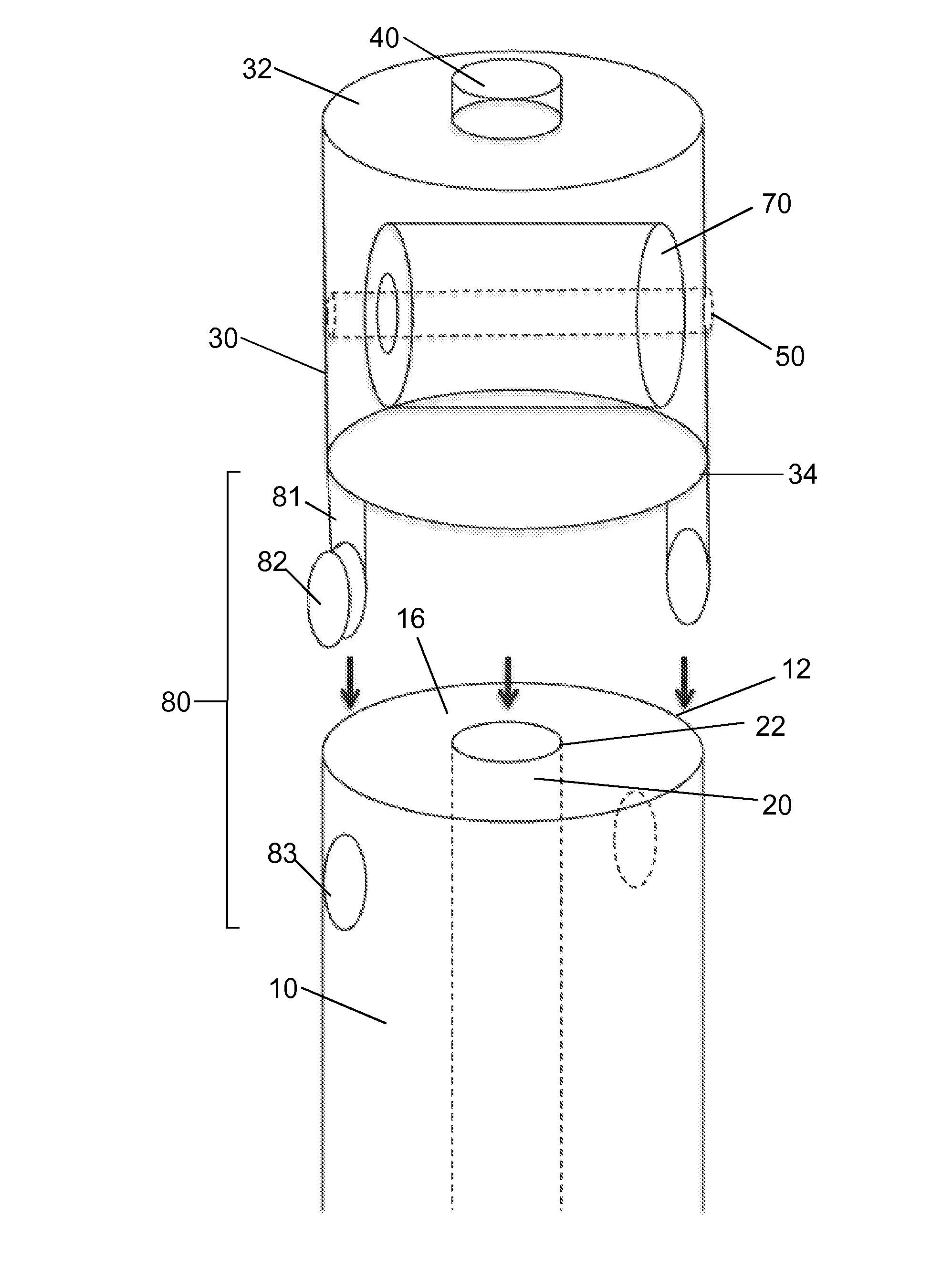
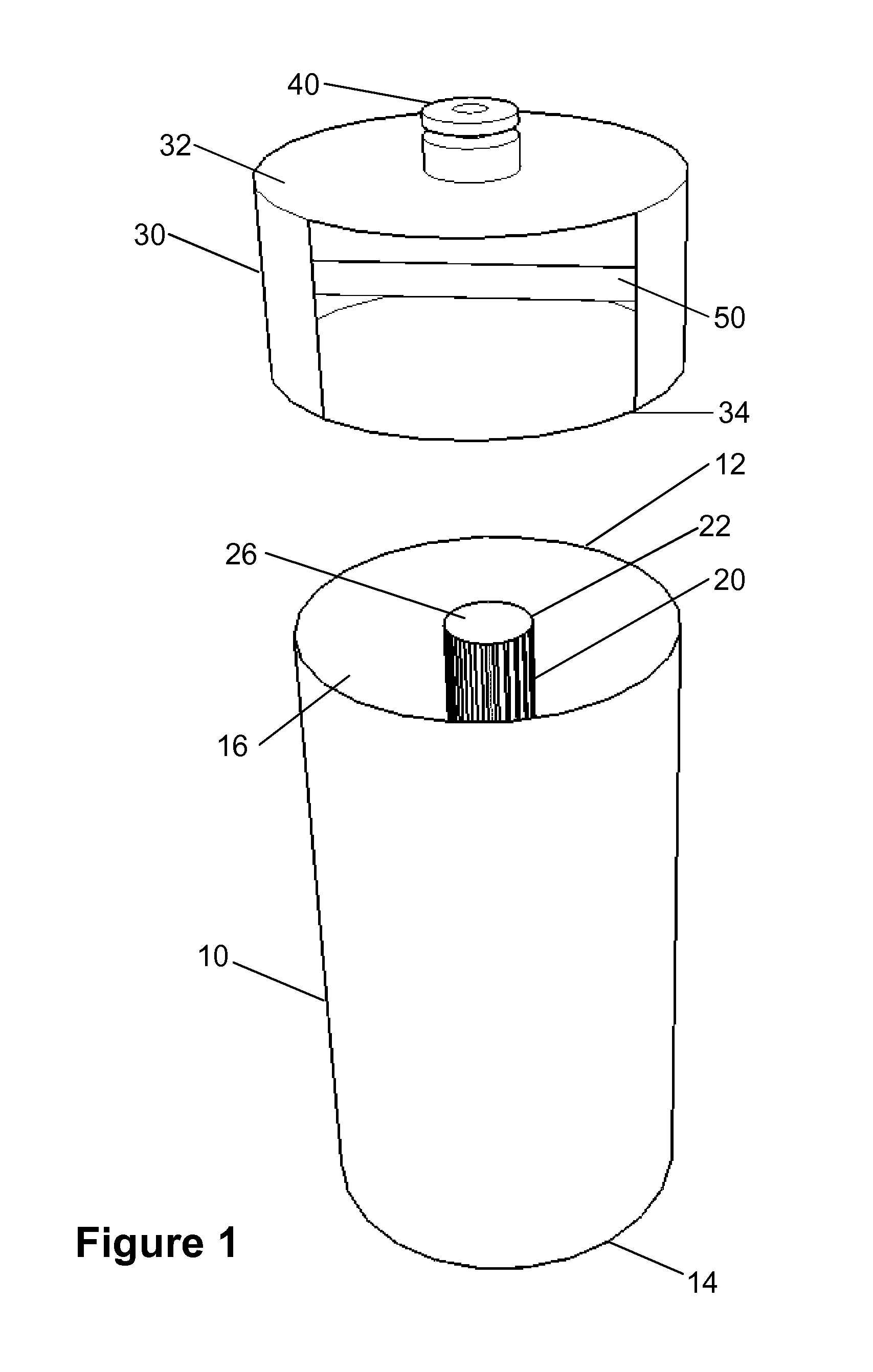
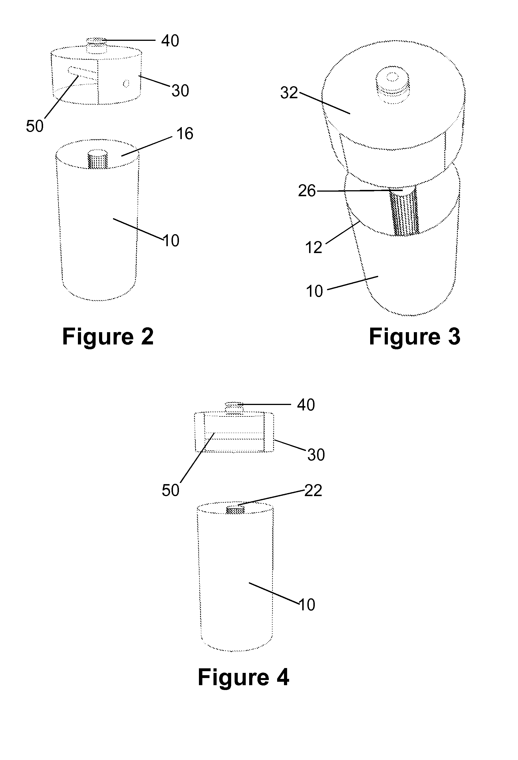
[0033]References will now be made in detail to the present exemplary embodiments, examples of which are illustrated in the accompanying drawings. Certain examples are shown in the above-identified figures and described in detail below. In describing these examples, like or identical reference numbers are used to identify common or similar elements. The figures are not necessarily to scale and certain features and certain views of the figures may be shown exaggerated in scale or in schematic for clarity and / or conciseness.

[0034]Referring now to the figures, apparatuses and methods are provided for ergonomically storing and concealing one or more lavatory products, supplies, and / or tools. Embodiments of the disclosed technology employ one or more hollow or semi-hollow modular sections for covering, concealing, receiving and / or storing one or more lavatory items.

[0035]The types of items that may be stored in embodiments of the disclosed technology may include any item associated with l...


PUM


Abstract

Embodiments of the disclosed technology are directed to an apparatus for storing and / or concealing lavatory and / or hygienic products. Specifically, the disclosed technology is directed to a housing having an at least partially hollowed interior portion. The interior portion is adapted to store, enclose and / or conceal a toilet stoppage release tool, such as, for example, a plunger or force cup. Any shape and / or style of plunger may be stored in the housing, including, but not limited to a standard plunger, a toilet plunger, a sink plunger, an accordion plunger and / or a taze plunger. The housing may also include a narrow shaft portion which may correspond and conform to the shaft of the plunger. The narrow portion may be adapted to receive and store toilet paper rolls such that the hollow core of the toilet paper rolls is axially disposed around the shaft.

Description

FIELD OF THE INVENTION[0001]The present invention relates to lavatory maintenance, particularly to an enclosure for storing and concealing toilet sanitation products and / or tools.BACKGROUND OF THE INVENTION[0002]A toilet plunger typically includes a handle and a suction head that is used to plunge a bathroom toilet by forcing air and / or liquid into and out of a drain opening, such as a drain pipe in a toilet bowl. Placement of an exposed toilet plunger in a bathroom is not aesthetically pleasing nor sanitary. On the other hand, when a toilet plunger is stored in an out of sight location, it may not be easily accessible when needed. Therefore, it is desirable to have a toilet plunger close at hand in a bathroom, preferably within a caddy or container as a plunger merely residing on a lavatory floor is unsightly.[0003]As such, many different stands, containers, and / or caddy assemblies for storing toilet plungers are known in the art. A storage container or vessel is desirable because ...

Claims


Application Information

Patent Timeline
Patent Type & Authority Applications(United States)
IPC IPC(8): A47K17/00E03C1/308B65D25/28B65D51/28A47K10/22B65D25/02
CPCA47K17/00A47K10/22E03C1/308B65D25/28B65D51/28B65D25/02A47K17/02E03D11/00
Inventor GORMELEY, ERIC J.
Owner GORMELEY ERIC J
Why Eureka
Try Eureka