Spinal Fusion Surgery Instrument for Implanting and Intervertebral Cage Thereof

a technology of implant instruments and cages, which is applied in the field of implant instruments and intervertebral cages, can solve the problems of operating surgical instruments and unable to exercise patients, and achieve the effect of simplifying the operation of implant instruments and reducing the arrangement time of intervertebral cages

Inactive Publication Date: 2016-11-03
INTAI TECH CORP
View PDF0 Cites 39 Cited by
  • Summary
  • Abstract
  • Description
  • Claims
  • Application Information

AI Technical Summary

Benefits of technology

[0008]In view of the aforementioned problem, a primary objective of the present invention provides a spinal fusion surgery instrument for implanting and an intervertebral cage thereof which change an angle with respect to the location of the intervertebral cage by adjusting the relative position between each member of the gripper subassembly, so that the complicated operation of the implant instrument is simplified to reduce the arrangement time of the intervertebral cage.
[0009]In view of the aforementioned problem, a primary objective of the present invention provides a spinal fusion surgery instrument for implanting to reduce the expected factors such as elastic fatigue, delayed movement and so on of the elastic member or the flexible member by adjusting the relative movement between the stiffener members, such that the uncertainty in the operational process can be avoided. In addition, the first fastening slot and the second fastening slot of the jaw portion can separate from the gripping end of the intervertebral cage by enabling the stop pin resists against the guiding shapes of the first gripping member and the second gripping member, such that the technical problems such as vibration, displacement and so on can be resolved when the implant instrument releases the intervertebral cage.
[0010]In view of the aforementioned problem, a primary objective of the present invention provides an intervertebral cage of a spinal fusion surgery, wherein the guiding end of the body thereof is a streamline shape with a sharp angle, which is able to peel off or penetrate the surrounding tissues of the intervertebral disks effortlessly and effectively reduce the residual force formed between the intervertebral disks. The dowel pins disposed in parallel are able to be gripped by the gripper subassembly of the implant instrument, and also applied in the positioning by the C-arm during the process of the surgery, such that the implanted direction and angle of the intervertebral cage of the present invention can be adjusted immediately by the relative position of the dowel pins and the auxiliary dowel pin, so as to shorten the positioning time.
[0019]Two dowel pins may be respectively inserted into the two dowel holes, and at least one auxiliary dowel pin may be inserted into the corresponding auxiliary dowel hole. The two dowel pins and the at least one auxiliary dowel pin may assist in displaying and guiding a dynamic relative location of the body in the process of the surgery, such that the positioning accuracy of the surgery can be promoted.
[0020]Preferably, the intervertebral cage may be shaped with a guided circumferential angle to avoid damaging surrounding tissues accidentally in the process of the surgery.

Problems solved by technology

When the intervertebral disk is damaged severely, two adjacent spine bones may approach with each other abnormally to suppress the surrounding nerves and the pain caused by the nerve compression may disable the patient from exercising.
When the implant instrument and the intervertebral cage are implanted into the human body, the surgeon can only operate the surgical instruments according the instinct, touch and experience as it is difficult to do through visual contact.

Method used


Image

  • Spinal Fusion Surgery Instrument for Implanting and Intervertebral Cage Thereof
  • Spinal Fusion Surgery Instrument for Implanting and Intervertebral Cage Thereof
  • Spinal Fusion Surgery Instrument for Implanting and Intervertebral Cage Thereof

Examples


Embodiment Construction

[0029]Hereinafter, embodiments of the present invention will be described in detail with reference to the accompanying drawings so that those skilled in the art to which the present invention pertains can realize the present invention. As those skilled in the art would realize, the described embodiments may be modified in various different ways, all without departing from the spirit or scope of the present invention.

[0030]The exemplary embodiments of the present invention will be understood more fully from the detailed description given below and from the accompanying drawings of various embodiments of the disclosure, which, however, should not be taken to limit the disclosure to the specific embodiments, but are for explanation and understanding only.

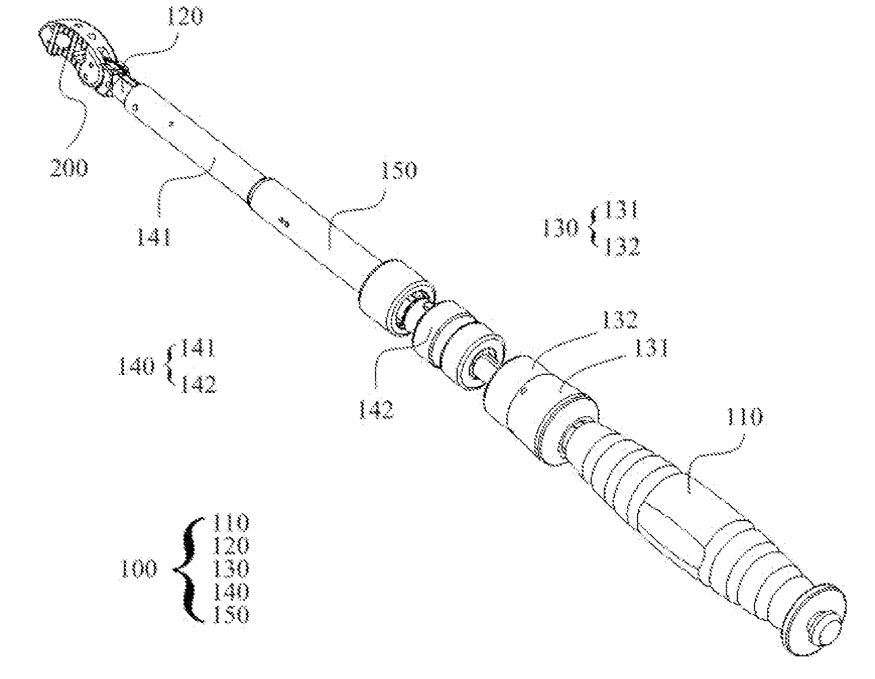
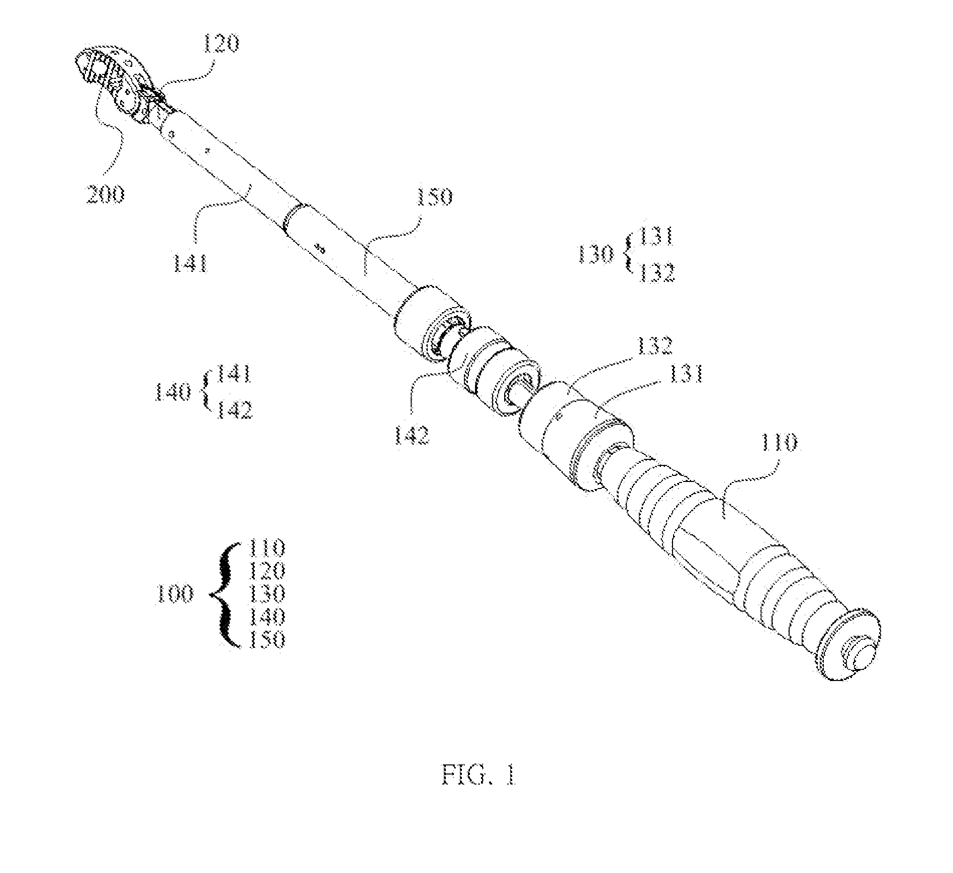
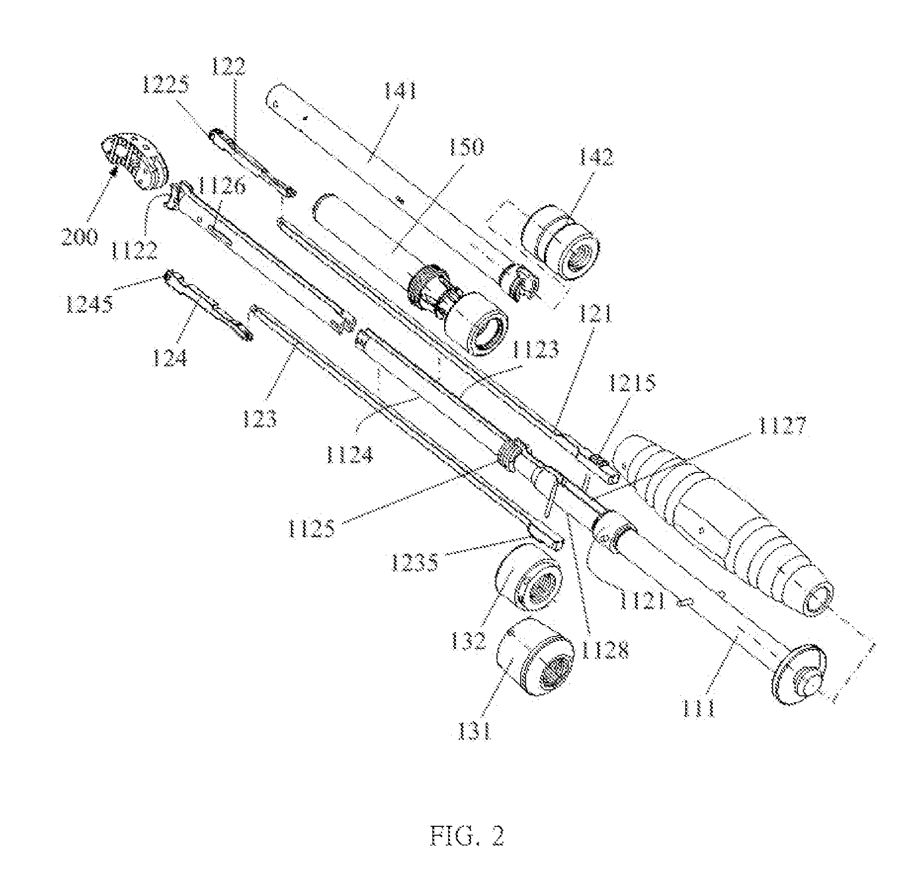
[0031]Please refer to FIG. 1, FIG. 2, and FIG. 3. As shown in the FIGS., an implant instrument 100, which may be a spinal fusion surgery instrument for implanting, of the present invention is applied to grip and implant an intervertebr...


PUM


Abstract

A spinal fusion surgery instrument for implanting and an intervertebral cage thereof are provided. The spinal fusion surgery instrument includes a body, a gripper subassembly, a first control subassembly, and a second control subassembly. The first control subassembly is provided to generate a displacement between a first connecting member and a second connecting member of the gripper subassembly to change the angle of gripper of the intervertebral cage. The second control subassembly is provided to enable a first gripper member and a second gripper member of the gripper subassembly separating smoothly from the dowel pins of the intervertebral cage. By means of the operation model, the spinal fusion surgery instrument may be controlled easily, and the orientation of the intervertebral cage may be promoted in the process of the surgery.

Description

CROSS-REFERENCE TO RELATED APPLICATION[0001]This application claims the benefit of Taiwan Patent Application No. 104113539, filed on Apr. 28, 2015, in the Taiwan Intellectual Property Office, the disclosure of which is incorporated herein in its entirety by reference.BACKGROUND OF THE INVENTION[0002]1. Field of the Invention[0003]The present invention generally relates to an implant instrument and an intervertebral cage thereof, in particular to the implant instrument and the intervertebral cage thereof which are feasible to be applied to the transforaminal lumbar interbody fusion (TLIF).[0004]2. Description of the Related Art[0005]Generally, the vertebrae disease is caused by long-term inappropriate pose, sport injury or comes with ages. When the intervertebral disk is damaged severely, two adjacent spine bones may approach with each other abnormally to suppress the surrounding nerves and the pain caused by the nerve compression may disable the patient from exercising.[0006]Current...

Claims


Application Information

Patent Timeline
Patent Type & Authority Applications(United States)
IPC IPC(8): A61F2/46A61F2/44
CPCA61F2/4611A61F2/4455A61F2002/4662A61F2002/4622A61F2/4657A61F2/442A61F2002/30112A61F2002/30471A61F2002/30538A61F2002/30784A61F2002/4627
Inventor CHO, MING-CHENGLIN, DIAN-YINGTSAI, YUNG-FANGCHUANG, SHIN-CHANG
Owner INTAI TECH CORP
Why Eureka
Try Eureka