Method and apparatus for fabricating containers
- Summary
- Abstract
- Description
- Claims
- Application Information
AI Technical Summary
Benefits of technology
Problems solved by technology
Method used
Image
Examples
first embodiment
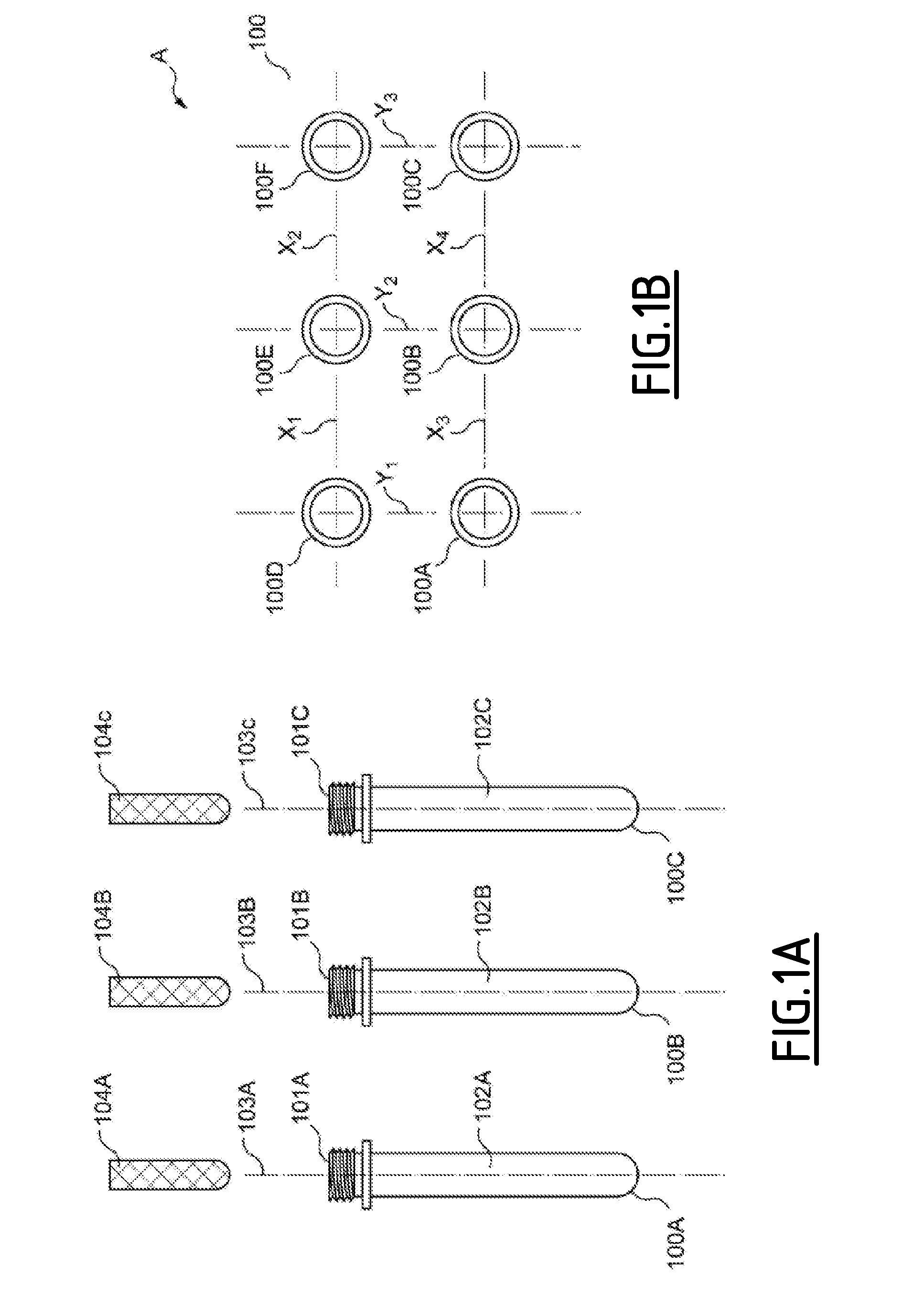
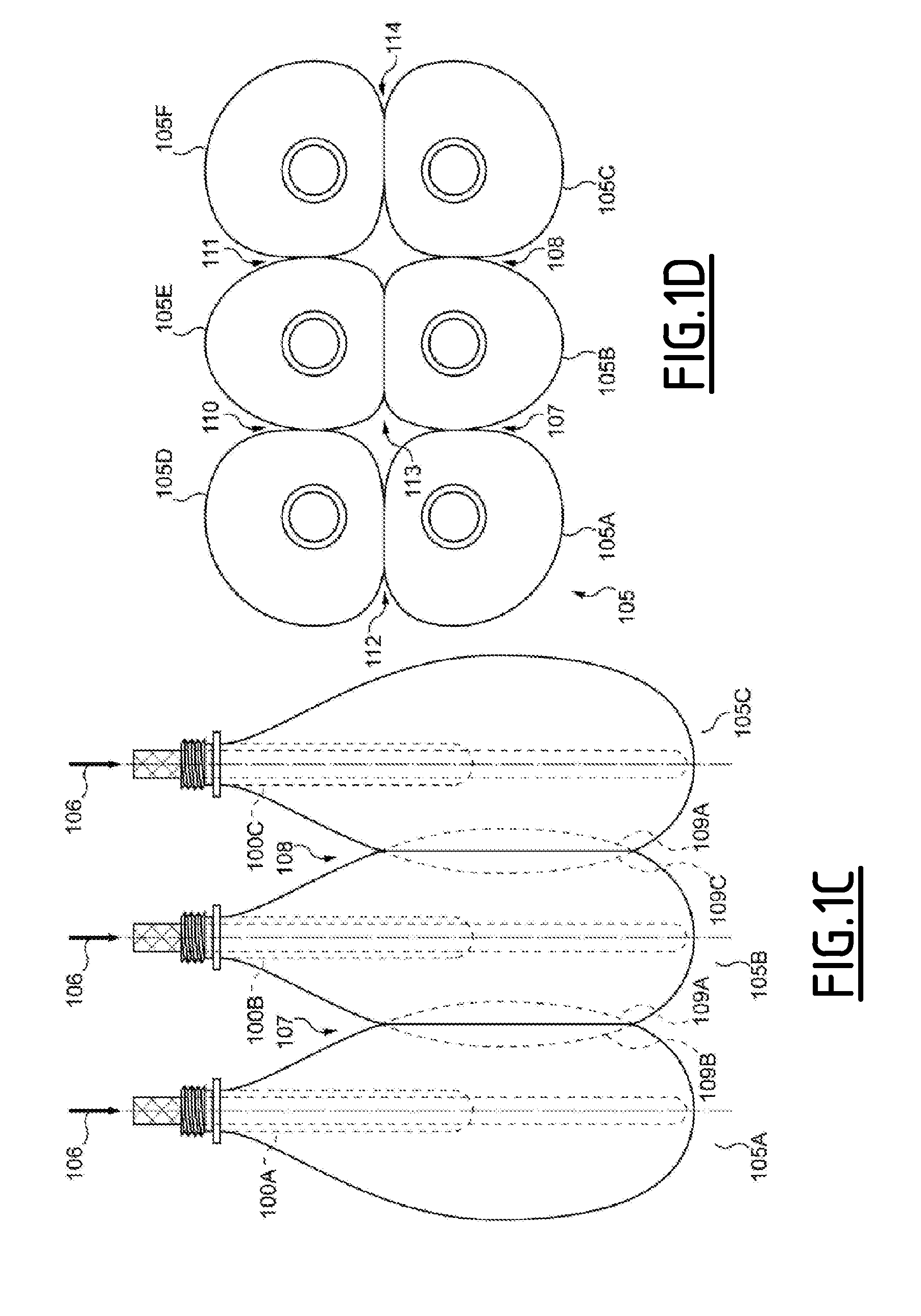
[0090]FIGS. 1A through 1D depict, respectively, a top view of a plurality of preforms prior to an injecting step; a side view of said plurality of preforms; a top view of a plurality of containers after said injecting step; and a side view of said plurality of containers, according to the invention.
[0091]FIG. 1A is a side view of a plurality of preforms 100A, 100B, &100C. The preforms 100A, 100B, &100C are of a type conventional to the art of container fabrication, having mouths 101A, 101B, 101C communicating respectively with a cavity 102A, 102B, 102C within the preform 100A, 100B, 100C.
[0092]During a positioning step of the method of the invention, the preforms 100A, 100B, 00C are disposed with the mouths 101A, 101B, 101C in substantially the same vertical orientation, said mouths 101A, 101B, 101C being, in this embodiment, oriented upwards. The longitudinal axes 103A, 103B, 103C of the preforms are thus parallel, the preforms 100A, 100B, 100C being substantially equally spaced fr...
second embodiment
[0107]FIGS. 2A through 2D depict respectively a top view of a plurality of preforms prior to an injecting step; a side section view of said plurality of preforms; a top view of a plurality of containers upon the completion of an injecting step; and a side section view of said plurality of containers, according to the invention.
[0108]FIG. 2A is a top view of an array B of preforms 200A, 200B, 200C, 200D, 200E, and 200F, disposed in an evenly-spaced 2×3 arrangement. The preforms 200 are disposed within a packaging element represented by the tray 201, which is comprised of a floor 202 disposed beneath the closed ends of the preforms and a wall 203 which extends from the perimeter of the floor 202.
[0109]FIG. 2B is a side section view of this arrangement, taken through the section line A-A depicted in FIG. 2A. Upon the injection of an incompressible fluid into the preforms 200, the tray 201 will serve to partially constrain the expansion of the preforms 200, leaving them free to expand i...
third embodiment
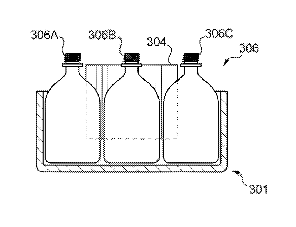
[0121]FIGS. 3A through 3D depict, respectively, a side section view, a top view, and two side section views of a series of steps for fabricating a plurality of containers according to the invention. FIG. 3A depicts three preforms 300A, 300B, 300C prior to an injection step, the preforms 300A, 300B, 300C being disposed in proximity to a constraining element 301 as in FIGS. 2A through 2D. The constraining element 301 has a concave, generally tub-shaped form, comprising as in the previous embodiment a floor 302 from the perimeter of which extends the wall 303.
[0122]There is further provided the shaping inserts 304, which is a specially-configured constraining element that is disposed within the constraining element 301 among the preforms 300. The shaping insert 304 extends from around the tops of the preforms 300 to the floor 302 of the constraining element 301. The form of the shaping insert 304 is now discussed.
[0123]FIG. 3B is a top view of the preforms 300A, 300B, 300C, 300D, 300E,...
PUM
| Property | Measurement | Unit |
|---|---|---|
| Temperature | aaaaa | aaaaa |
| Pressure | aaaaa | aaaaa |
| Diameter | aaaaa | aaaaa |
Abstract
Description
Claims
Application Information
 - R&D
- Intellectual Property
- Life Sciences
- Materials
- Tech Scout
- Unparalleled Data Quality
- Higher Quality Content
- 60% Fewer Hallucinations
Browse by: Latest US Patents, China's latest patents, Technical Efficacy Thesaurus, Application Domain, Technology Topic, Popular Technical Reports.
© 2025 PatSnap. All rights reserved.Legal|Privacy policy|Modern Slavery Act Transparency Statement|Sitemap|About US| Contact US: help@patsnap.com


