A method and apparatus for fabricating containers

Active Publication Date: 2016-11-03
DISCMA
View PDF22 Cites 4 Cited by
  • Summary
  • Abstract
  • Description
  • Claims
  • Application Information

AI Technical Summary

Benefits of technology

The patent describes a way to make containers easier to manipulate and work with. This is done by using an overwrap that binds the containers together. This makes it possible to make packages of different sizes and numbers of containers, while keeping the cost and complexity of the container process low. As a result, the efficiency of making and distributing containers is improved.

Problems solved by technology

However, in the case of pressurized gas blow molding technology such systems are disadvantageous in that, as with the traditional pressurized-gas blow molding systems, one may not fabricate multiple containers at once without furnishing a mold for each container to be fabricated with each cycle of the apparatus.
Such molds are complex and thus often expensive and time-consuming to fabricate, particularly in the quantities that are required for the operation of a high-volume container fabricating installation such as a beverage bottling line.
The prior art is insufficient to resolve this issue.
However, GARWOOD does not fabricate a plurality of containers, but merely a single double-chambered container; the two chambers cannot be separated without breaking, cutting, or otherwise permanently modifying the container.
Nor does GARWOOD resolve the expense required in furnishing mold assemblies for each container being fabricated.
Moreover, the use of such molds also lengthens the container fabrication cycle, in that it requires time to open and close the mold, and to insert the parison(s) and extract the finished container.
This additional time lengthens the duration of a container fabrication cycle and therefore comprises a limitation on the output of a container fabrication system.
A further constrain to be mentioned in the case of use of pressurized gas blow molding technology is that the control and coordination of pressurized gas injection for simultaneous injections has not been yet optimized.
Finally, such systems are disadvantageous in that any additional packaging elements, such as labels or bindings, must be provided in a separate step with separate equipment.
This adds further complication and expense to the operation of a container production installation.

Method used


Image

  • A method and apparatus for fabricating containers
  • A method and apparatus for fabricating containers
  • A method and apparatus for fabricating containers

Examples


first embodiment

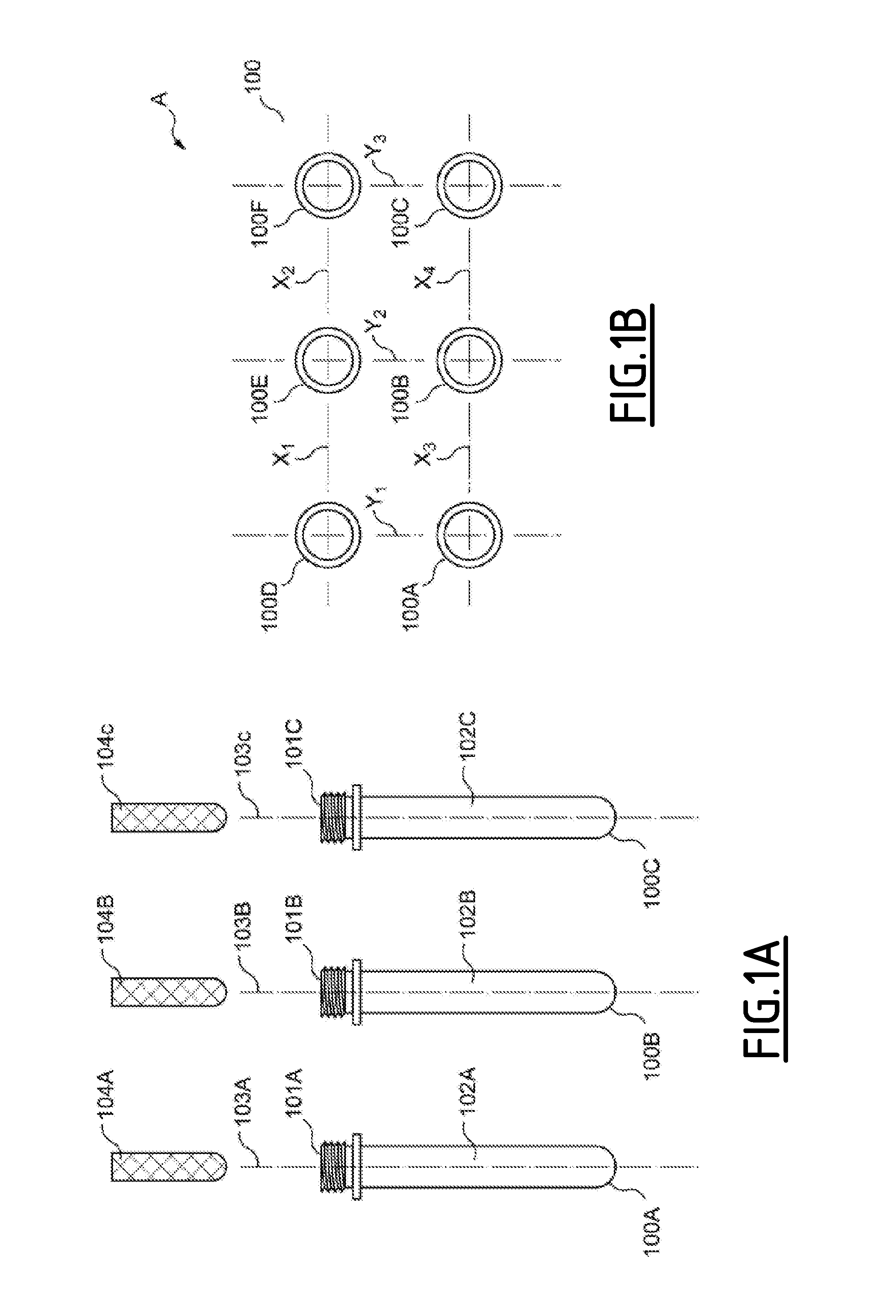
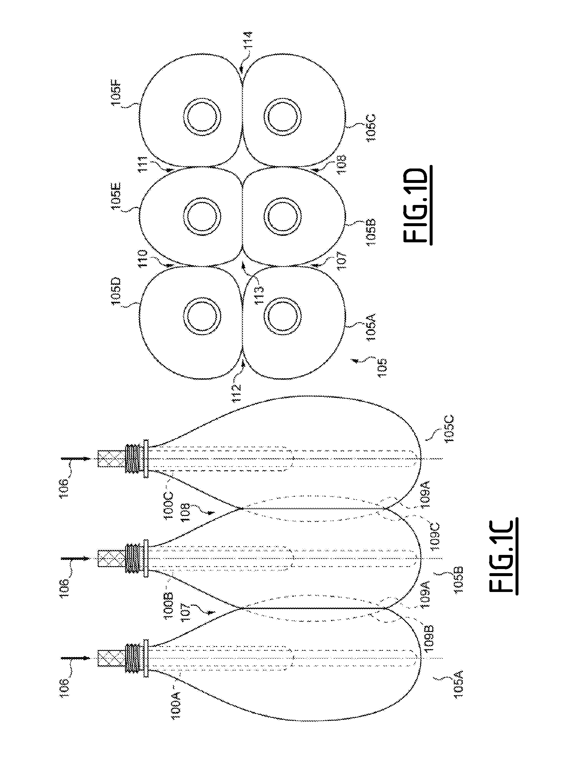
[0098]FIGS. 1A through 1D depict, respectively, a top view of a plurality of preforms prior to an injecting step; a side view of said plurality of preforms; a top view of a plurality of containers after said injecting step; and a side view of said plurality of containers, according to the invention.

[0099]FIG. 1A is a side view of a plurality of preforms 100A, 100B, &100C. The preforms 100A, 100B, &100C are of a type conventional to the art of container fabrication, having mouths 101A, 101B, 101C communicating respectively with a cavity 102A, 102B, 102C within the preform 100A, 100B, 100C.

[0100]During a positioning step of the method of the invention, the preforms 100A, 100B, 100C are disposed with the mouths 101A, 101B, 101C in substantially the same vertical orientation, said mouths 101A, 101B, 101C being, in this embodiment, oriented upwards. The longitudinal axes 103A, 103B, 103C of the preforms are thus parallel, the preforms 100A, 100B, 100C being substantially equally spaced f...

second embodiment

[0115]FIGS. 2A through 2D depict respectively a top view of a plurality of preforms prior to an injecting step; a side section view of said plurality of preforms; a top view of a plurality of containers upon the completion of an injecting step; and a side section view of said plurality of containers, according to the invention.

[0116]FIG. 2A is a top view of an array B of preforms 200A, 200B, 200C, 200D, 200E, and 200F, disposed in an evenly-spaced 2×3 arrangement. The preforms 200 are disposed within a packaging element represented by the tray 201, which is comprised of a floor 202 disposed beneath the closed ends of the preforms and a wall 203 which extends from the perimeter of the floor 202.

[0117]FIG. 2B is a side section view of this arrangement, taken through the section line A-A depicted in FIG. 2A. Upon the injection of an incompressible fluid into the preforms 200, the tray 201 will serve to partially constrain the expansion of the preforms 200, leaving them free to expand i...

third embodiment

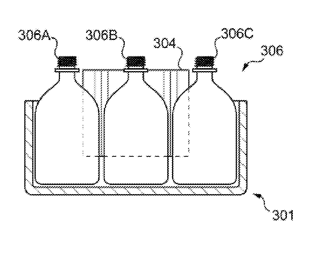
[0129]FIGS. 3A through 3D depict, respectively, a side section view, a top view, and two side section views of a series of steps for fabricating a plurality of containers according to the invention. FIG. 3A depicts three preforms 300A, 300B, 300C prior to an injection step, the preforms 300A, 300B, 300C being disposed in proximity to a constraining element 301 as in FIGS. 2A through 2D. The constraining element 301 has a concave, generally tube-shaped form, comprising as in the previous embodiment a floor 302 from the perimeter of which extends the wall 303. There is further provided the shaping inserts 304, which is a specially-configured constraining element that is disposed within the constraining element 301 among the preforms 300. The shaping insert 304 extends from around the tops of the preforms 300 to the floor 302 of the constraining element 301. The form of the shaping insert 304 is now discussed.

[0130]FIG. 3B is a top view of the preforms 300A, 300B, 300C, 300D, 300E, and...


PUM

PropertyMeasurementUnit
Sizeaaaaaaaaaa
Volumeaaaaaaaaaa
Shapeaaaaaaaaaa

Abstract

A plurality of containers fabricated from plastic preforms, wherein the form of each of the containers is partially defined, through expansion of the containers by other containers adjacent thereto.A package including a plurality of the plastic containers is also provided.

Description

CROSS-REFERENCE TO RELATED APPLICATIONS[0001]This application is the U.S. National phase of PCT application no. PCT / EP2014 / 078078 filed on Dec. 16, 2014, which claims priority to EP13197336.4 filed on Dec. 16, 2013, the disclosures of which are incorporated in their entirety by reference herein.TECHNICAL FIELD[0002]The invention relates to a plurality of containers for liquid contents and to a package comprising a plurality of containers.[0003]The application discloses a method for fabricating said containers, and an apparatus for carrying out such a method, and the containers produced by it.BACKGROUND OF THE INVENTION[0004]It has long been known to fabricate containers by blow-molding, wherein a preform is inflated into the form of a container by the injection of a pressurized gas therein. The preform generally comprises a hollow, tubular body fabricated from a thermoplastic resin, having a cavity, a plain closed end, and a finished open end generally provided with threads or other...

Claims


Application Information

Patent Timeline
IPC IPC(8): B29C49/00B29C49/24B65D71/06B29C49/06B65D21/02B65D25/20B29C49/12B29C49/46
CPCB29C49/0042B29C49/12B29C49/24B29C49/46B29C49/06B29L2031/7158B65D25/205B65D71/06B29C2049/4664B29K2101/12B65D21/0205B29C2049/023B29C49/42802B29C49/42808B29C49/48185B65B3/022B65B7/16
Inventor DRZEWIECKI, FREDERICHARTWIG, KLAUSKANNENGIESSER, DAMIEN
Owner DISCMA
Why Eureka
Try Eureka