

Auto-tracking imaging apparatus
- Summary
- Abstract
- Description
- Claims
- Application Information
AI Technical Summary
Benefits of technology
Problems solved by technology
Method used
Image

Examples
Embodiment Construction
[0045]Hereinafter, referring to accompanying drawings, embodiments of an auto-tracking imaging apparatus according to the present invention will be described.
[0046]
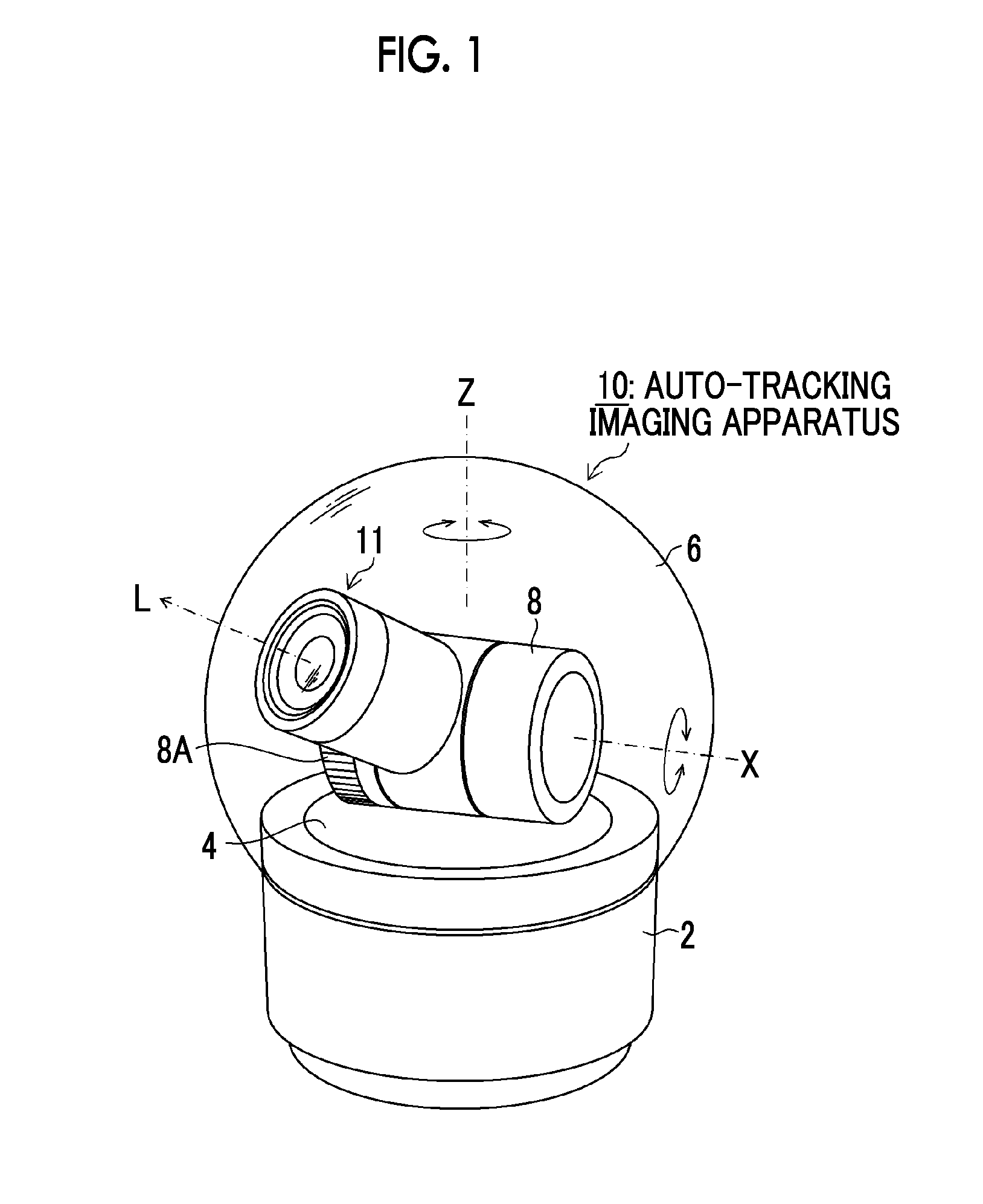
[0047]FIG. 1 is a perspective view of an appearance of an auto-tracking imaging apparatus according to the present invention.
[0048]As shown in FIG. 1, an auto-tracking imaging apparatus 10 mainly has an apparatus main body 2, an imaging section 11, a panning / tilting device 30 (FIG. 5), and a dome cover 6 that covers the imaging section 11.
[0049]The panning / tilting device 30 has a pedestal 4 and a holding section 8 that is fixed onto the pedestal 4 and rotatably holds the imaging section 11.
[0050]The pedestal 4 is disposed to be rotatable about the axis of the vertical direction Z of the apparatus main body 2. A pan driving section 34 (FIG. 5) rotates about the axis of the vertical direction Z.
[0051]The holding section 8 has a gear 8A that is provided on the axis the same as the axis of the horizontal direction X, and tran...
PUM
 Abstract
Description
Claims
Application Information