
High efficiency power controller for luminaire

a power controller and high efficiency technology, applied in the field of illumination, can solve the problems of significant changes in light output, damage to solid-state light sources, and significant energy consumption of interior and exterior spaces of street lighting, and achieve the effect of improving the power factor of the illumination system

Active Publication Date: 2016-11-03
EXPRESS IMAGING SYST
View PDF9 Cites 6 Cited by
  • Summary
  • Abstract
  • Description
  • Claims
  • Application Information

AI Technical Summary

Benefits of technology

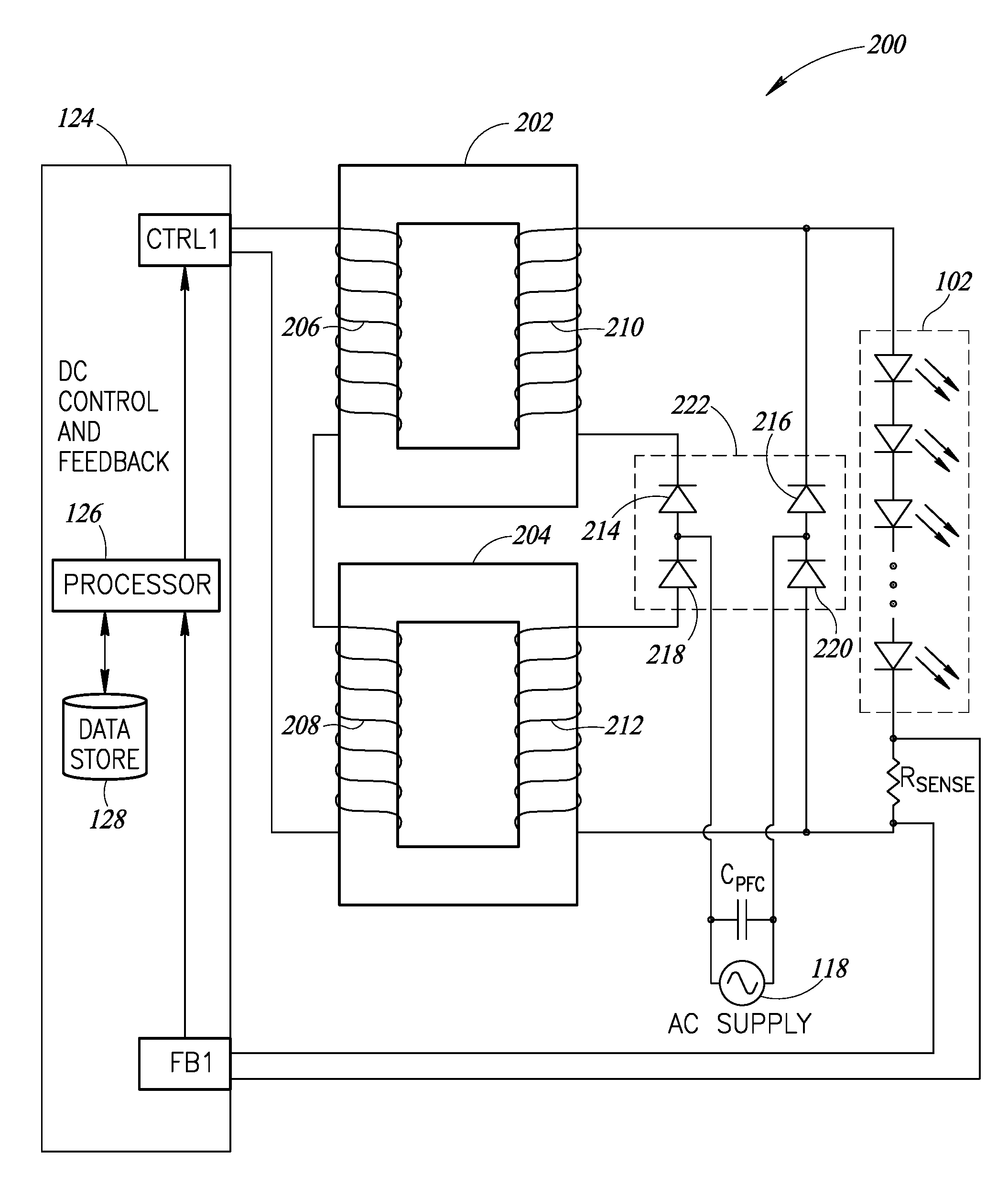
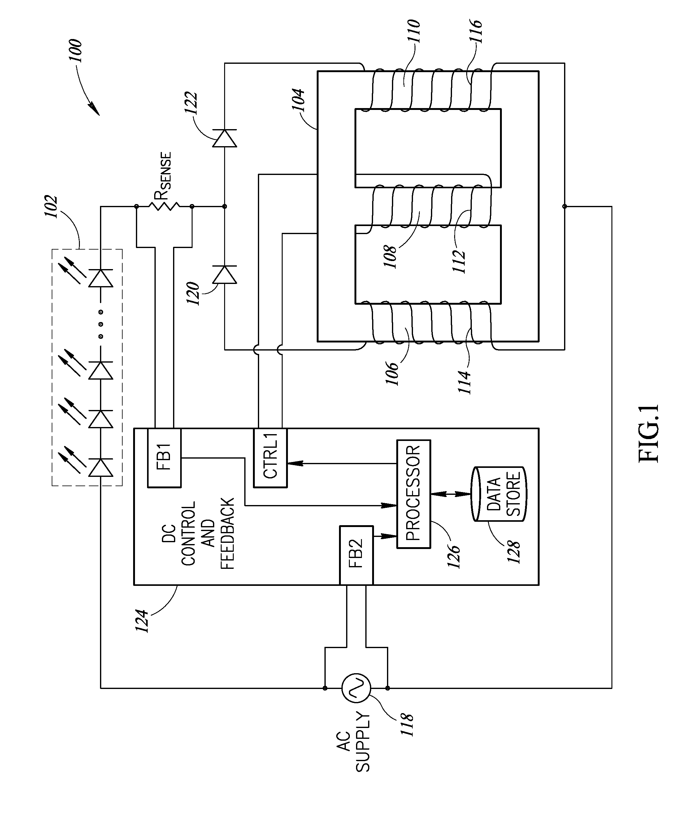
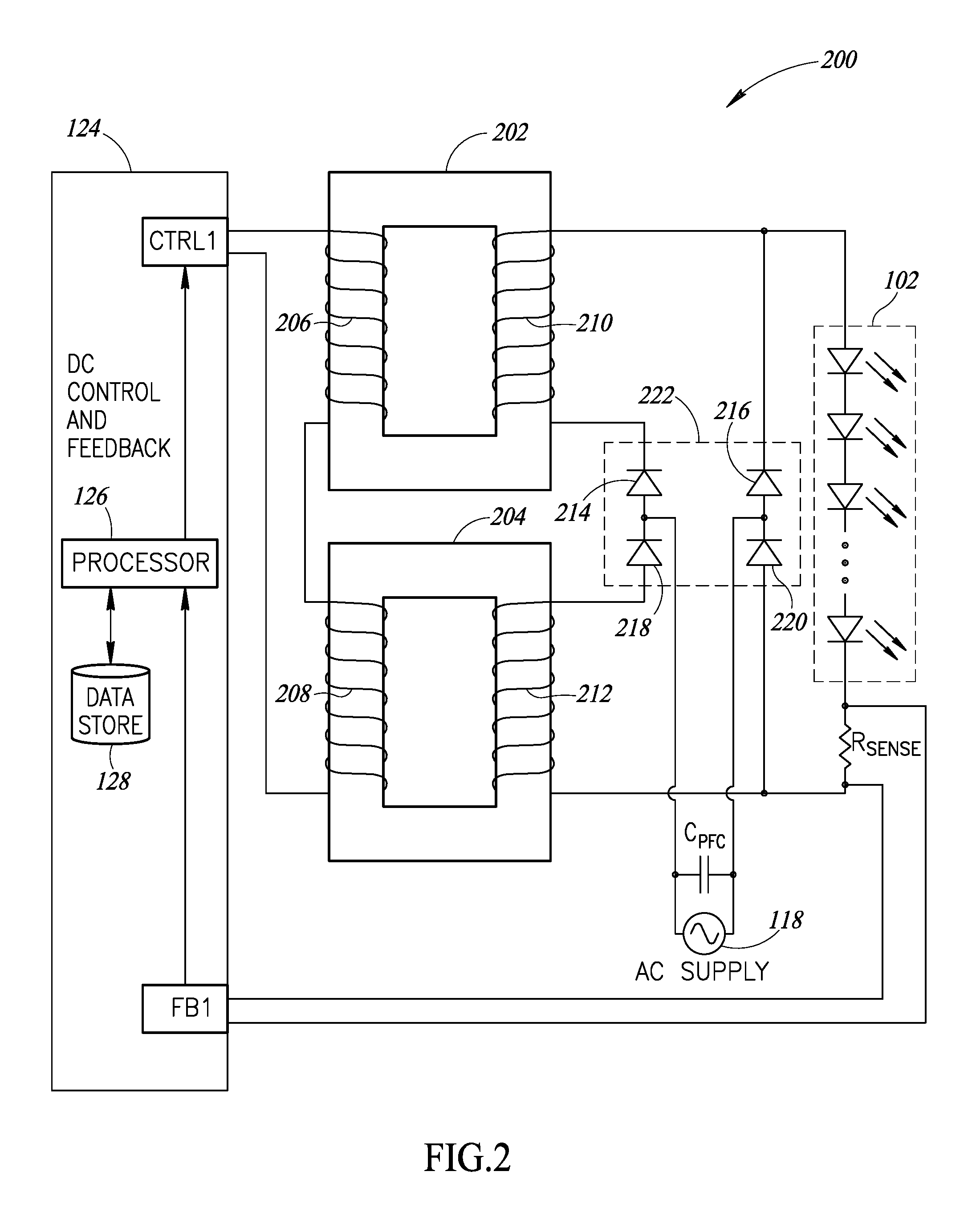
The patent is describes a method and apparatus for efficiently controlling the flow of current in a lighting system. The method involves receiving an alternating current signal and a feedback signal that indicates the direct current flow through the light sources. The feedback signal helps to control the flow of direct current through control windings, which in turn affect the power factor of the illumination system. The method also involves increasing the frequency of the rectified current signal to reduce the detectability of amplitude variations. The apparatus includes solid-state rectifiers to rectify the alternating current signal. The technical effects of this patent include improved power factor correction and more efficient control of current flow in a lighting system.

Problems solved by technology

Residential, commercial, and street lighting which illuminate interior and exterior spaces consume a significant amount of energy.
These large variations in current will cause significant changes in light output and possibly damage the solid-state light source(s) by exceeding its rated power handling capacity.

Method used


Image

  • High efficiency power controller for luminaire
  • High efficiency power controller for luminaire
  • High efficiency power controller for luminaire

Examples


Embodiment Construction

[0023]In the following description, certain specific details are set forth in order to provide a thorough understanding of various disclosed embodiments. However, one skilled in the relevant art will recognize that embodiments may be practiced without one or more of these specific details, or with other methods, components, materials, etc. In other instances, well-known structures associated with the various embodiments have not been shown or described in detail to avoid unnecessarily obscuring descriptions of the embodiments.

[0024]Unless the context requires otherwise, throughout the specification and claims that follow, the word “comprising” is synonymous with “including,” and is inclusive or open-ended (i.e., does not exclude additional, unrecited elements or method acts).

[0025]Reference throughout this specification to “one embodiment” or “an embodiment” means that a particular feature, structure or characteristic described in connection with the embodiment is included in at lea...


PUM

PropertyMeasurementUnit
constant forward voltageaaaaaaaaaa
voltageaaaaaaaaaa
voltageaaaaaaaaaa

Abstract

Systems, methods and articles for providing lighting or illumination systems having drive circuits that employ a magnetic amplifier (“mag-amp”) and one or more feedback circuits to form a power converter that powers solid-state light sources (e.g., LEDs). The magnetic amplifier includes one or more magnetic cores which provides a controllable reluctance for magnetic flux. The magnetic amplifier includes one or more power windings which receive energy from an alternating current (AC) supply (e.g., AC mains) and delivers rectified AC current as direct current (DC) to one or more solid-state light sources. The magnetic amplifier includes one or more control windings coupled to a DC control source. The drive circuit may have two or more rectifiers (e.g., solid-state rectifiers) to provide a direct current to drive the solid-state light sources and also to isolate the one or more control windings from interference from the magnetic flux of the one or more power windings.

Description

BACKGROUND[0001]1. Technical Field[0002]The present disclosure relates to illumination, and more particularly to efficient power control for illumination systems.[0003]2. Description of the Related Art[0004]Luminaires enjoy widespread use in a variety of industrial, commercial, and municipal applications. Such applications can include general or area lighting of workspaces, roadways, parking lots, and the like. Multiple luminaires are typically arranged in patterns and positioned at intervals sufficient to provide a minimum overall level of illumination across the area of interest. For example, luminaires may be spaced at intervals along a driveway in a multilevel parking garage to provide an overall level of illumination that permits safe ingress and egress by pedestrians as well as permits safe operation of motor vehicles within the parking garage. In a similar manner, luminaires may be spaced at intervals throughout a commercial center parking lot to promote safe operation of mot...

Claims


Application Information

Patent Timeline
Patent Type & Authority Applications(United States)
IPC IPC(8): H05B33/08H02M1/42H01F27/24H02M7/06H05B44/00
CPCH05B33/0851H05B33/0809H05B33/0884H01F27/24H02M7/06H02M1/4208H05B33/0827H05B45/382H05B45/10H05B47/20H05B45/46
Inventor REED, WILLIAM G.
Owner EXPRESS IMAGING SYST
Learn More