Smoking apparatus: flat smoking pipe

a smoking apparatus and flat technology, applied in the field of smoking apparatus and the method of tobacco, can solve the problem of intentionally restricting the flow of air by any existing smoking device, and achieve the effect of reducing the risk of smoking tobacco

Inactive Publication Date: 2016-11-10
QUALITICS
View PDF5 Cites 58 Cited by
  • Summary
  • Abstract
  • Description
  • Claims
  • Application Information

AI Technical Summary

Benefits of technology

[0007]It is the object of present invention to teach the means of using Vortical Boiling Phenomenon of heat exchange at the convective cooling for cooling of smoke inside the smoking pipe up to full recuperation with the temperature of the human body before this smoke has reached the person's lungs. The invented smoking pipe offers the means for making a full draw of the desired dosage of smoke into the lungs using minimal suction effort.

Problems solved by technology

The only obstacle is the limited flow of air intentionally restricted by any existing smoking device.

Method used


Image

  • Smoking apparatus: flat smoking pipe
  • Smoking apparatus: flat smoking pipe
  • Smoking apparatus: flat smoking pipe

Examples


Embodiment Construction

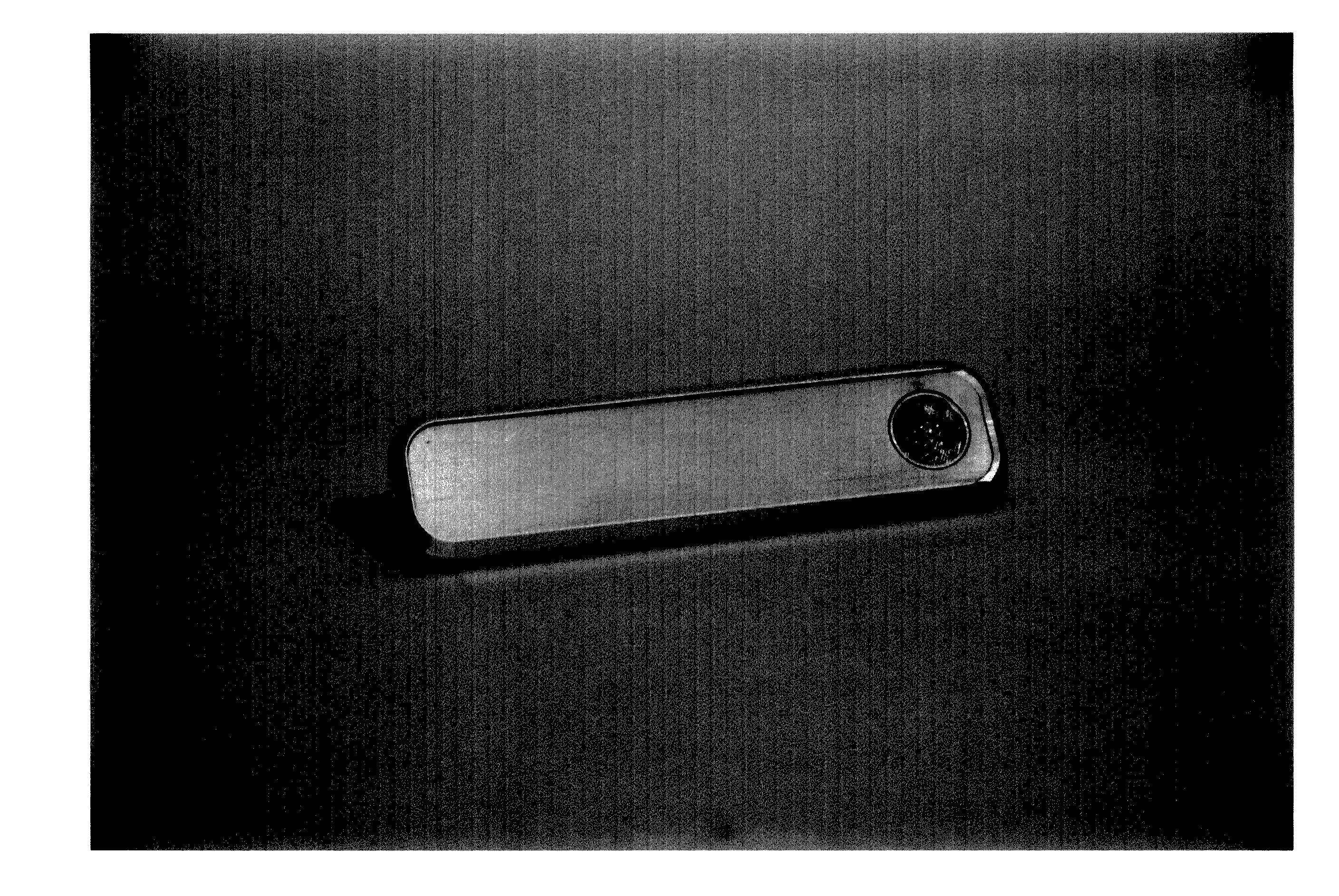
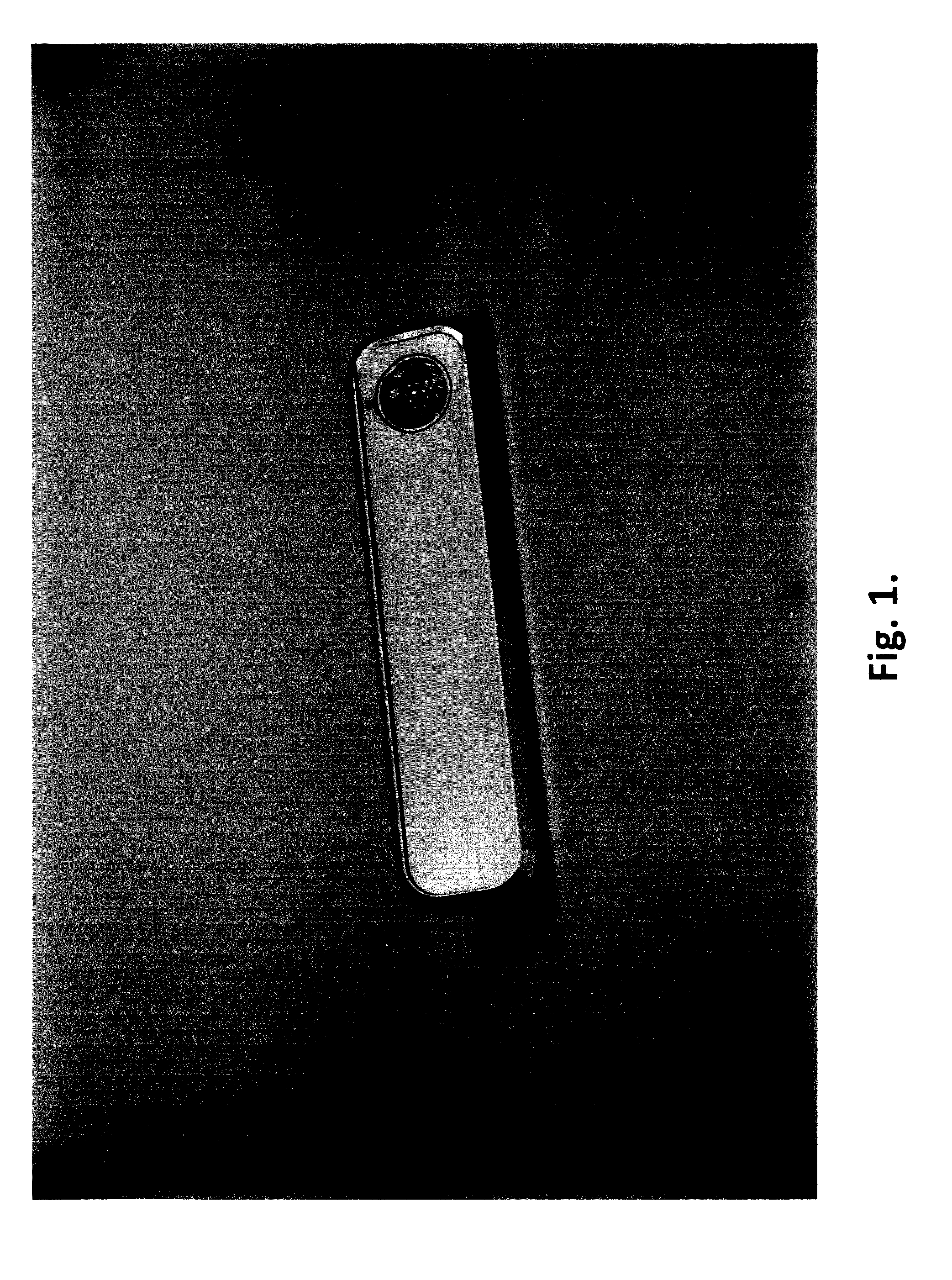
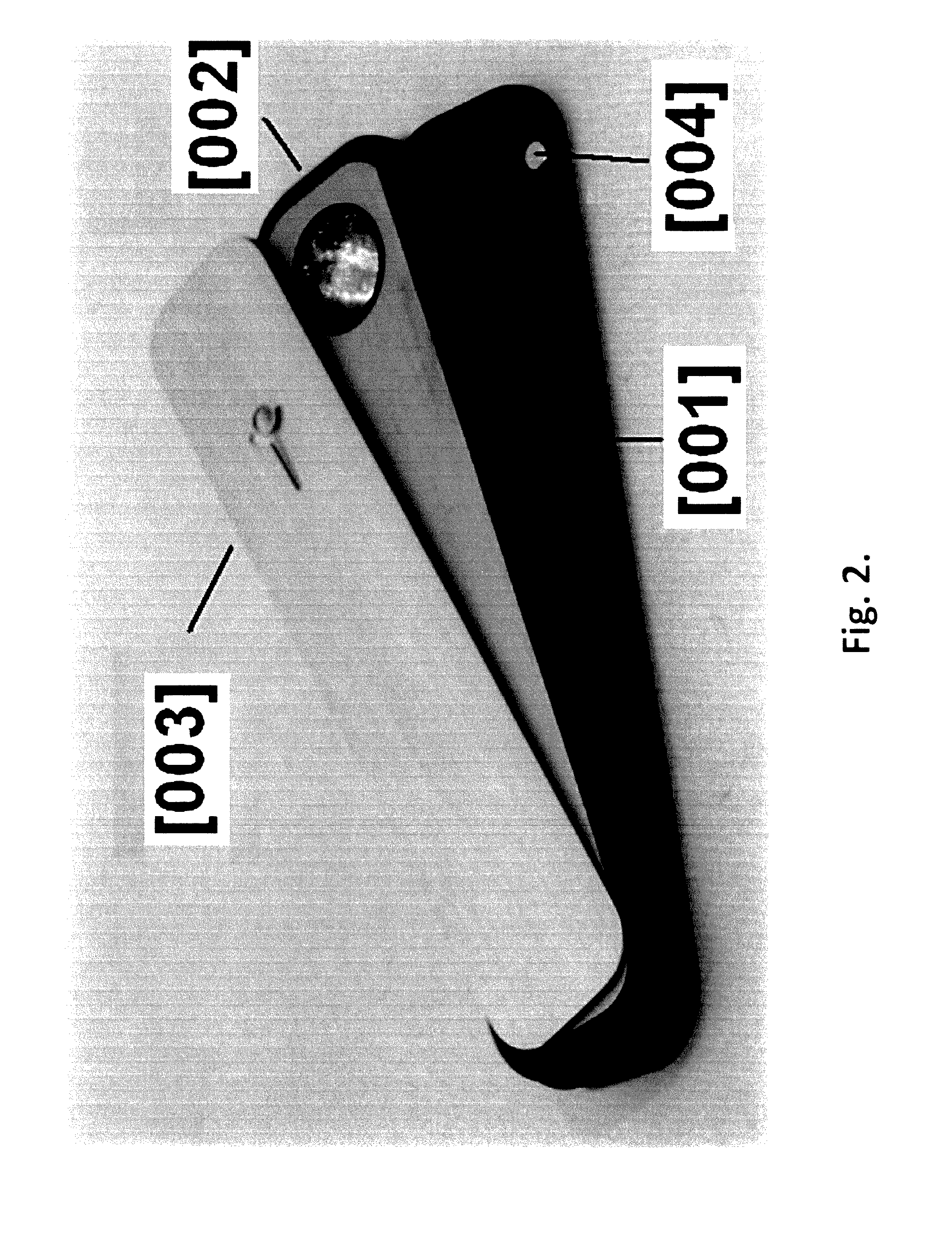
[0021]The common view of the preferred embodiment of the present invention is shown in FIG. 1. FIG. 2 represents the preferred embodiment as a rectangular aluminum body comprising three parts: the top [001], the bottom [002] and the sliding cover [003] that, being attached to each other, will form the body that is shown in FIG. 1 and will be held in such configuration by the system of magnets [004] that are placed in bulk of part [001] and part [002]. The method of attachment of said two parts of the smoking pipe is not principal as long as it can serve the natural need to disassemble smoking pipe for the occasional cleaning of its internal surfaces. Screws, build-in clasps, complementary magnets, or other means can be used to keep the two parts of smoking pipe together. In the preferred embodiment the set of holes [005] is drilled for the said magnets.

[0022]FIG. 3 shows the drawings of the top part [001] of the smoking pipe in details. As one can see, this part is made of rectangul...


PUM


Abstract

The present invention describes the flat smoking pipe with advanced smoking effect. The invented smoking pipe offers the means for making a full draw of the low temperature smoke into the lungs using minimal suction effort.

Description

[0001]The present invention incorporates methods that were invented in U.S. Pat. No 8,496,048 B2 and claims priority under U.S. Provisional Patent No. 61 / 997,198.BACKGROUND OF THE INVENTION[0002]1. Field of the Invention[0003]The present invention relates generally to an apparatus for and the method of smoking tobacco and other inhalation materials.[0004]2. Description of the Related Art[0005]The difficulty of creating the balance between the natural ability of human lungs to create the pressure drop and desired dosage of smoke intake while inhaling has always been the biggest problem of smoking. The main factor that is causing just said problem is the temperature of the smoke. From the point of view of Physics, the peculiarity of the smoking process is evident: the same suction effort of smoker that provides a flux of ambient air used for burning the certain amount of smoke-producing material is continuing to carry the produced hot smoke directly into the person's lungs. Delivery o...

Claims


Application Information

Patent Timeline
Patent Type & Authority Applications(United States)
IPC IPC(8): A24F1/00
CPCA24F1/00
Inventor YANKELEVICH, DMITRY
Owner QUALITICS
Why Eureka
Try Eureka