
Quick release fastener

Inactive Publication Date: 2016-11-10
LIN HSI TONG
View PDF2 Cites 2 Cited by
  • Summary
  • Abstract
  • Description
  • Claims
  • Application Information

AI Technical Summary

Benefits of technology

The invention is a fastener that can quickly attach or release things. Its technical effect is to offer a quick and efficient way to connect and disconnect items.

Problems solved by technology

It may spend much time and labor.
There is no easy and fast solution in the market.

Method used


Image

  • Quick release fastener
  • Quick release fastener
  • Quick release fastener

Examples


Embodiment Construction

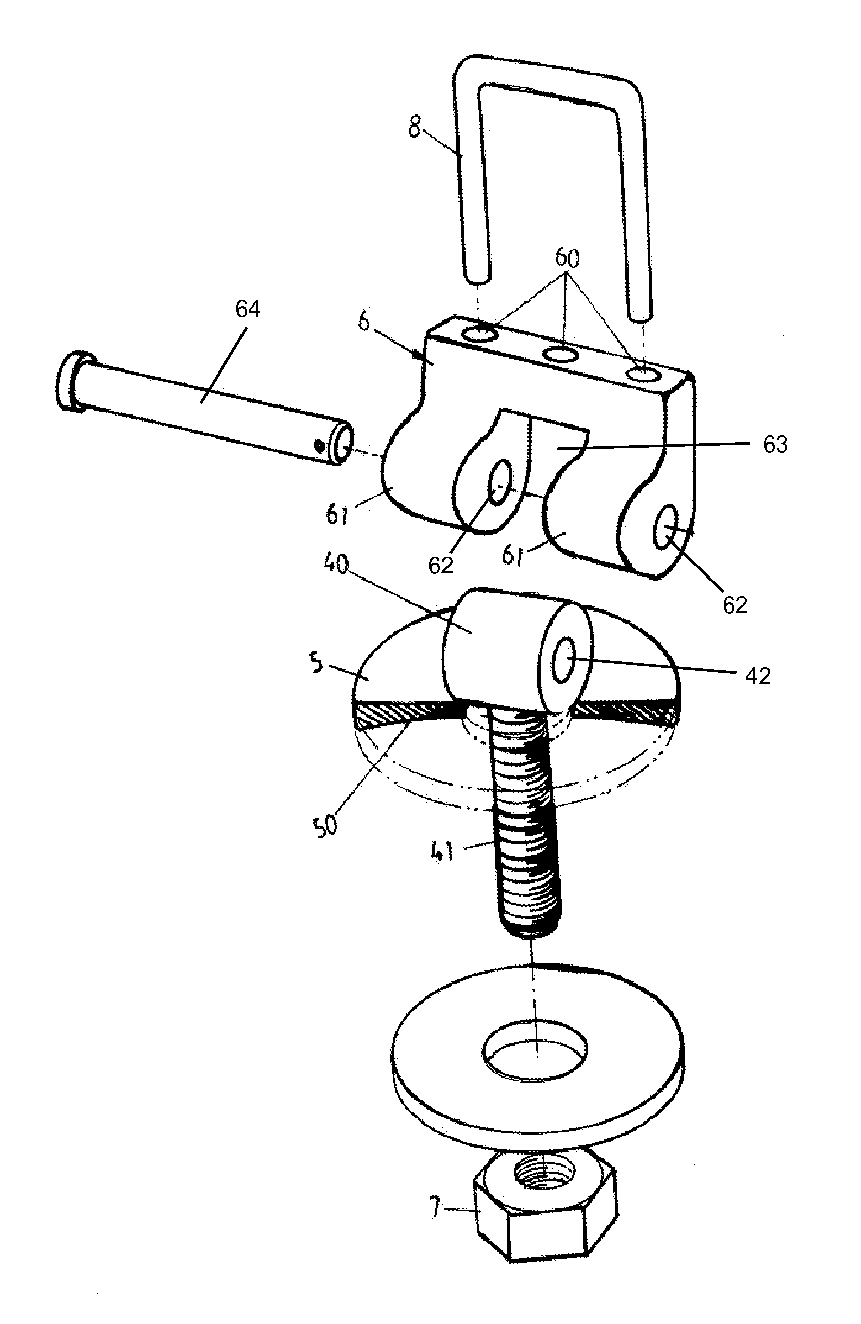
[0015]Please refer to FIGS. 4-7. The quick release fastener of the invention includes a threaded rod 41, a head 40, a pressing washer 5 and a rotator 6. The head 40 is firmly connected on an end of the threaded rod 41. The head 40 is a hollow cylinder with a central hole 42. The central hole 42 and the head 40 are coaxial. An axis of the head 40 is perpendicular to that of the threaded rod 41. The pressing washer 5 is an independent annular piece. The pressing washer 5 is passed through by the threaded rod 41 and placed under the head 40. The rotator 6 is a U-shaped body with two symmetrical and parallel cams 61 and a recess 63 therebetween. Each of the two cams 61 has a pivot hole 62. The two pivot holes 62 align with each other.

[0016]The recess 63 is substantially identical to the head 40 in shape. Thus the head can be embedded in the recess 63. A pivot 64 is inserted into the two pivot holes 62 and the central hole 42 to make the rotator rotatable. The threaded rod 41 can be rota...


PUM


Abstract

The invention includes a threaded rod, a head, a pressing washer and a rotator. The head is firmly connected on an end of the threaded rod and is a hollow cylinder with a central hole. An axis of the head is perpendicular to that of the threaded rod. The pressing washer is passed through by the threaded rod and placed under the head. The rotator is a U-shaped body with two symmetrical and parallel cams and a recess therebetween. Each of the two cams has a pivot hole. The head is embedded in the recess, and a pivot is inserted into the two pivot holes and the central hole. The two cams progressively press or release the pressing washer while the rotator is being rotated about the pivot.

Description

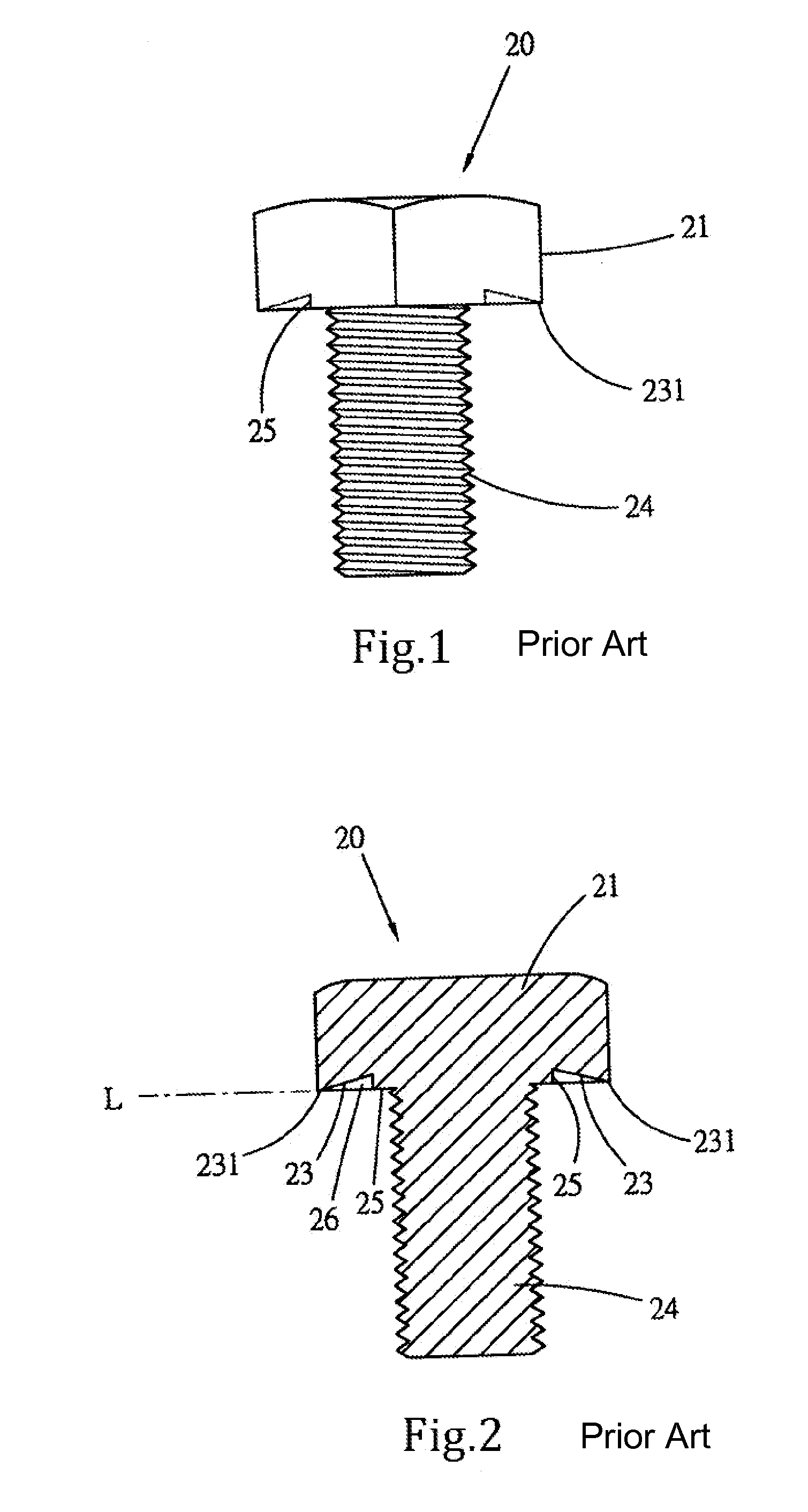
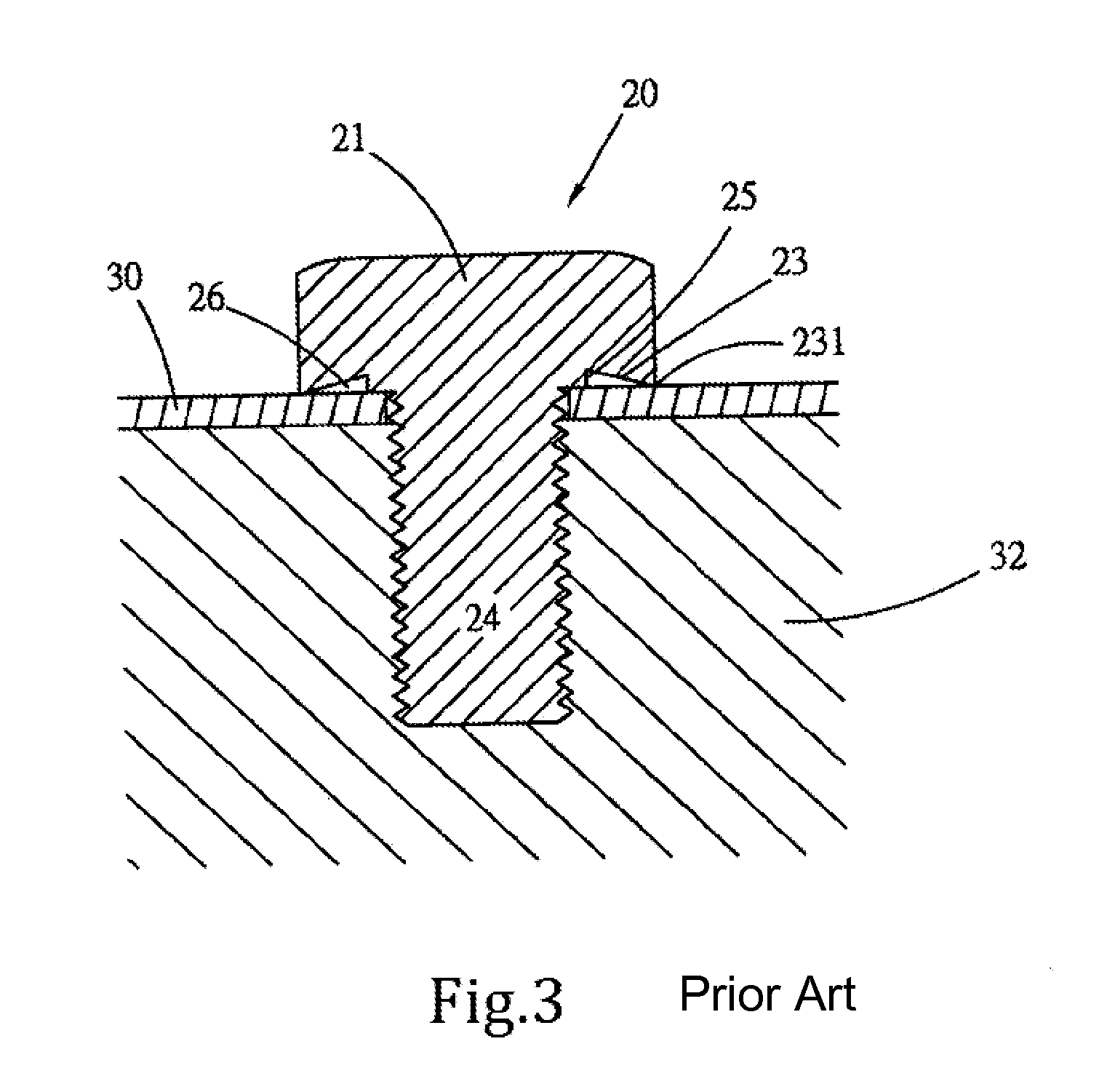
BACKGROUND OF THE INVENTION[0001]1. Technical Field[0002]The invention relates to bolts, particularly to quick release bolts.[0003]2. Related Art[0004]A conventional bolt 20, as shown in FIGS. 1-3, includes a head 21, a threaded rod 24 and a pressing portion 25. The bottom of the head 21 is formed with a conic surface 23 which inclines outwards and forms an acute-angled edge 231. The pressing portion 25 surrounds the threaded rod 24 and abuts against the conic surface 23. The pressing portion 25 and the acute angled edge 231 are coplanar on plane L. A conic space 26 is formed in the conic surface 23. When a workpiece 30 is fastened onto a substrate 32, the connection between the head 21 and the workpiece 30 is annular but not planar. This can improve fastening strength of bolt.[0005]However, the bolt 20 must be progressively rotated to finish fastening. It may spend much time and labor. There is no easy and fast solution in the market.SUMMARY OF THE INVENTION[0006]An object of the i...

Claims


Application Information

Patent Timeline
IPC IPC(8): F16B39/02F16B43/00
CPCF16B43/00F16B39/02F16B2/185F16B5/0642
Inventor LIN, HSI-TONG
Owner LIN HSI TONG
Learn More