Terminator bracket assembly
- Summary
- Abstract
- Description
- Claims
- Application Information
AI Technical Summary
Benefits of technology
Problems solved by technology
Method used
Image
Examples
first embodiment
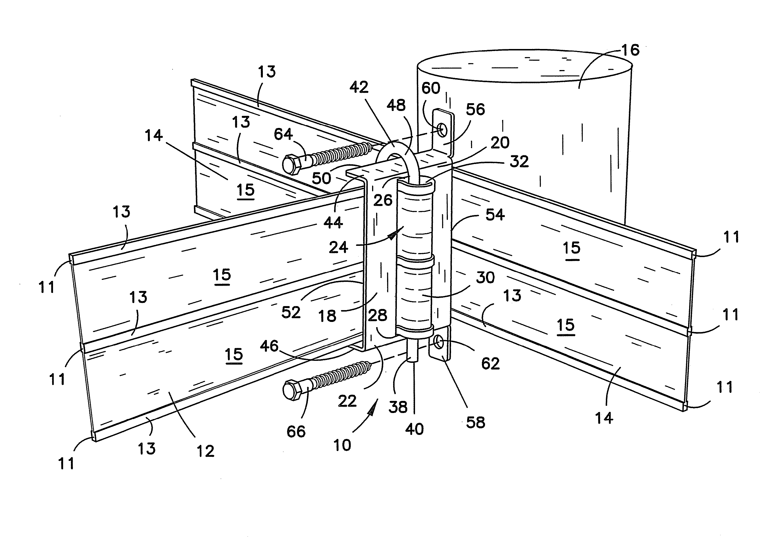
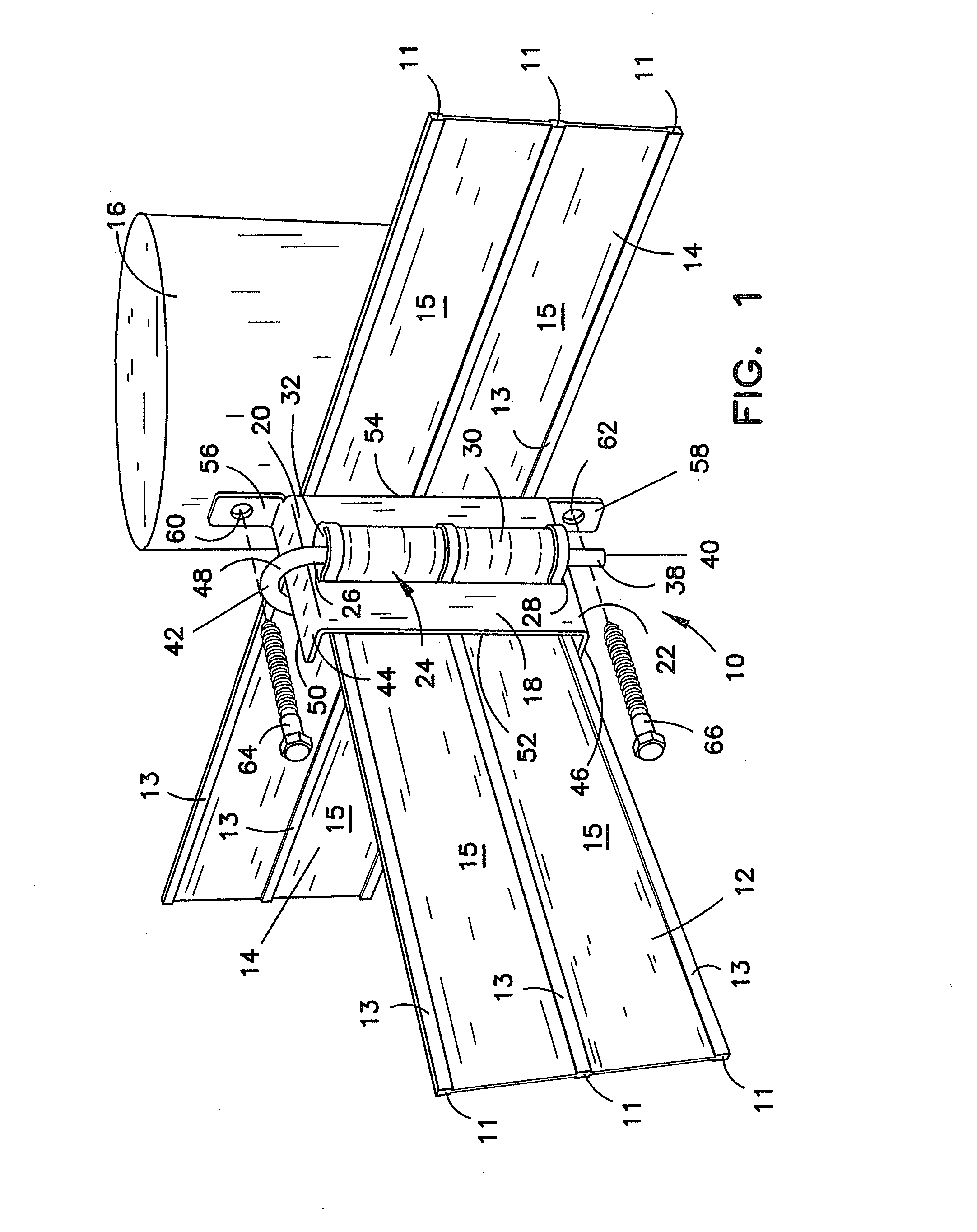
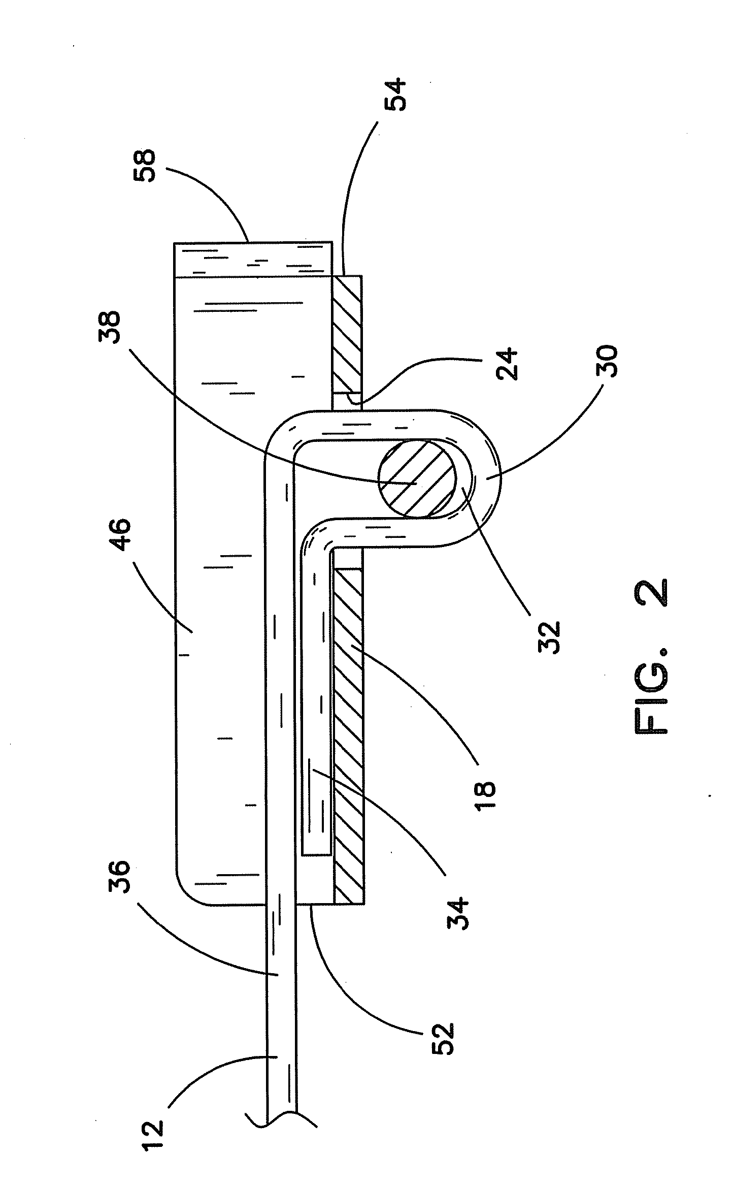
[0024]The plate 18 is shown in FIGS. 1 and 2 to include a third edge 52 extending between the first and second edges 20, 22 generally parallel to the slot 24. A fourth edge 54 is located opposite the third edge 52. The fourth edge 54 is shown to be generally parallel to the third edge 52. Tabs 56 and 58 extend outward from the rearwardly projecting flanges 44 and 46, respectively, in general alignment with the fourth edge 54. Each of the tabs 56 and 58 include an opening 60 and 62, respectively. Fasteners 64 and 66 can couple the tabs 56 and 58 to an adjacent fence post 16 thereby securing the first polymer jacketed high tensile wire fencing 12 to the fence post 16. The fourth edge 54 of the plate 18 is shown in FIG. 1 to be positioned so that the tabs 56, 58 straddle a second polymer jacketed high tensile wire fencing 14 to secure the second fencing 14 to an adjacent fence post 16. In this manner, the terminator bracket assembly 10 is able to connect two separate lengths of the pol...
third embodiment
[0029]a terminator bracket assembly 10 includes a pin 38 has a lower end 40 and an upper end 42 separated from each other such that the pin 38 has a length which is greater than the distance between the upper end 26 and the lower end 28 of the slot 24. In FIGS. 5-7, the pin 38 is shown to be inserted into the bight 32 in the fold 30 of the fencing 12. The upper end 42 of the pin 38 is shown to engage the first edge 20 of the plate 18 to retain the fold 30 of the fencing 12 in the slot 24. The first and second edges 20, 22 of the plate 18 are shown to include a rearwardly projecting flange 44, and 46, respectively. The upper end 42 of the pin 38 is shown to include a bend 48 of sufficient size to extend over a rear edge 50 of the rearwardly projecting flange 44 of the first edge 20 while the opposite end contacts the plate surface adjacent to the lower edge 22 and the pin 38 is engaged in the bight 32. The pin 38, and particularly the lower end 40 of the pin 38, is dimensioned such t...
PUM
 Abstract
Description
Claims
Application Information
 - R&D
- Intellectual Property
- Life Sciences
- Materials
- Tech Scout
- Unparalleled Data Quality
- Higher Quality Content
- 60% Fewer Hallucinations
Browse by: Latest US Patents, China's latest patents, Technical Efficacy Thesaurus, Application Domain, Technology Topic, Popular Technical Reports.
© 2025 PatSnap. All rights reserved.Legal|Privacy policy|Modern Slavery Act Transparency Statement|Sitemap|About US| Contact US: help@patsnap.com


