
Rope suspension device with at least one rope suspension module

Active Publication Date: 2016-12-22
AIRBUS HELICOPTERS DEUT GMBH
View PDF1 Cites 2 Cited by
  • Summary
  • Abstract
  • Description
  • Claims
  • Application Information

AI Technical Summary

Benefits of technology

The present invention provides a rope suspension device for a rotorcraft that allows for quick and safe release of suspended ropes in any operating condition. The device complies with safety regulations and requirements and has a simple design that allows for secure and reliable release of ropes. The device also includes a dampening element to prevent excessive movement of the load beam after unlocking. This makes the device safer and more reliable for use in special operations and cargo transportation.

Problems solved by technology

However, conventional rope suspension devices are usually not adapted for allowing a quick release of a suspended rope if the rope is under tension, due to a comparatively high reacting force on an underlying release mechanism.
Nevertheless, e.g. in a rescue situation, a helicopter may not provide a sufficiently stable platform and in case of winds or gust there is a high risk for injury of the cabin operator when trying to cut the rope with the knife.
In this case, it would not be possible for the clasp to open under the stresses of the loaded rope, because the force exerted by the ring against the clasp can in no case stress the latter in the opening direction.
However, this means that in this rope suspension device an application of force along the rope in a direction that points away from the rope suspension device strongly pivots the clasp towards its closed position, so that a required actuation force for activating, i.e. operating the handle would be so high, that it would not be possible for an operator to release the rope.
Thus, an easy and quick release of the rope under any foreseeable condition is not guaranteed, especially if the 3.5 g and a safety factor of 1.5 according to the latest certification requirements according to FAR29 / CS29 and FAR27 / CS27 are applied.
Furthermore, this rope suspension device is comparatively complex and requires a multiplicity of constituent components, each of which could at least in part cause an unintended opening of the rope suspension device in case of a failure.
However, this quick rope release device is not installed in the helicopter, but on the harness, which is close to the person on the rope.
Thus, if the rope is e.g. jammed under a stone or other item, it cannot be released quickly from within the helicopter and a cabin operator within the helicopter is again needed for cutting the rope by means of a knife.

Method used


Image

  • Rope suspension device with at least one rope suspension module
  • Rope suspension device with at least one rope suspension module
  • Rope suspension device with at least one rope suspension module

Examples


Embodiment Construction

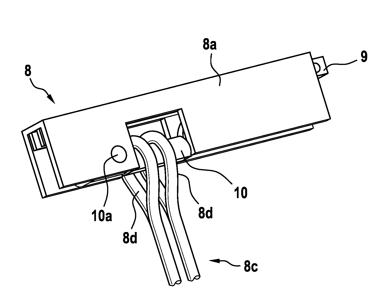
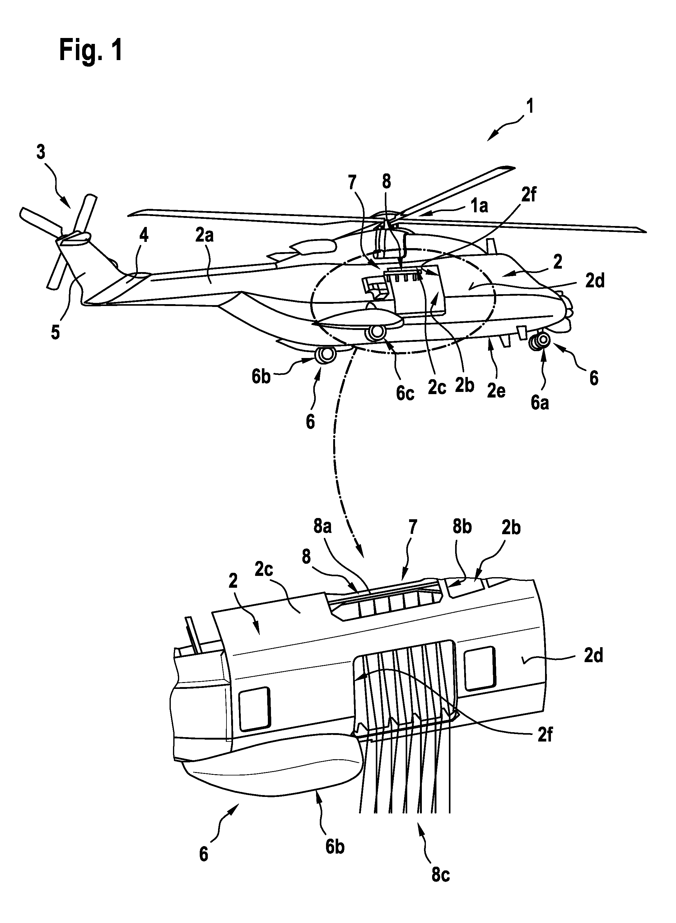
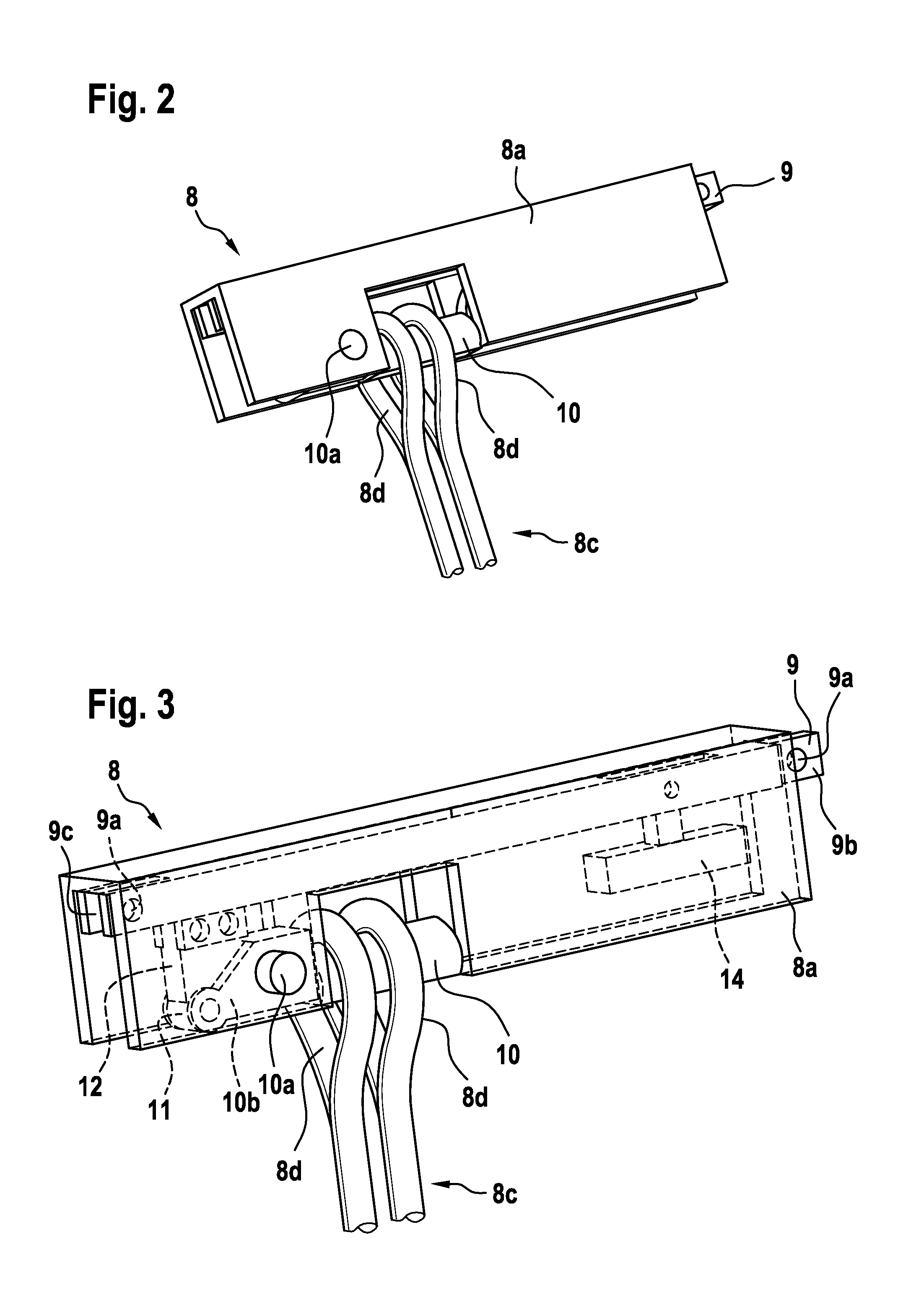
[0043]FIG. 1 shows a rotorcraft 1, which is by way of example embodied, and therefore hereinafter for simplicity also referred to, as a helicopter. The helicopter 1 illustratively comprises a fuselage 2 with a bottom shell 2e and a starboard side wall 2d that is provided with a starboard side sliding door opening 2f. On the helicopter's board side, the fuselage 2 preferably comprises a board side wall that is provided with a board side sliding door opening. The fuselage 2 exemplarily further comprises a tail boom 2a and a cabin 2b with a cabin ceiling 2c.

[0044]The helicopter 1 illustratively comprises a landing gear 6, which is exemplarily embodied as a wheel-type landing gear that comprises associated landing gear nose wheels 6a, a board side rear wheel 6b and a starboard side rear wheel 6c. The helicopter 1 illustratively further comprises at least one main rotor la configured to provide lift and forward or backward thrust during operation, and at least one counter-torque device ...


PUM


Abstract

A rope suspension device with at least one rope suspension module that is adapted for suspension of at least one rope from a rotorcraft, the rope suspension module comprising at least one lockable load beam that is rotatable around an axis of rotation between a locked state and an unlocked state and that is adapted for supporting in the locked state at least one rope that is to be suspended from the rope suspension module, the at least one lockable load beam being, upon unlocking in operation, rotatable from the locked state around the axis of rotation into the unlocked state at least on the basis of a load that is applied to the at least one lockable load beam by means of at least one rope that is supported by the at least one lockable load beam.

Description

CROSS REFERENCE TO RELATED APPLICATION[0001]This application claims priority to European patent application No. EP 15400025.1 filed on Jun. 22, 2015, the disclosure of which is incorporated in its entirety by reference herein.BACKGROUND OF THE INVENTION[0002](1) Field of the Invention[0003]The invention is related to a rope suspension device with at least one rope suspension module that is adapted for suspension of at least one rope from a rotorcraft, said rope suspension device comprising the features of claim 1.[0004](2) Description of Related Art[0005]Rotorcrafts, and in particular helicopters, are commonly used for rappelling, extraction and insertion tasks during special helicopter operations using suitable ropes that are suspended from the helicopters. For instance, helicopters are used for rapidly descending, i.e. rappelling, of persons from a given height, for extracting persons from a given area and / or for inserting persons into a given area. Furthermore, helicopters are us...

Claims


Application Information

Patent Timeline
IPC IPC(8): B64D1/22F16M13/02
CPCF16M13/02B64D1/22B64D47/00
Inventor BEHRENS, MICHAELSTUETZ, RAINER
Owner AIRBUS HELICOPTERS DEUT GMBH
Learn More