Seal assembly for a sterile environment

a sterile environment and seal technology, applied in the field of seals, can solve the problems of inconvenient manufacturing, inability to allow the contents of the sterile bag, and difficulty in mixing or otherwise agitating the sterile contents inside the bio-reactor, so as to maintain sterility and maintain sterility

Active Publication Date: 2016-11-10
TRELLEBORG SEALING SOLUTIONS GERMANY
View PDF18 Cites 3 Cited by
  • Summary
  • Abstract
  • Description
  • Claims
  • Application Information

AI Technical Summary

Benefits of technology

[0014]An advantage of the present invention is the seal carried by the seal carrier can maintain sterility after the hermetic seal is abraded away, allowing the pass-through to maintain sterility during multiple agitations.
[0015]Another advantage is more than one seal carried by one or more seal carriers can allow for a high number of agitations before the seal assembly can no longer maintain sterility.
[0016]Yet another advantage is purging gas can be introduced into the space to maintain a positive pressure within the space that keeps contaminants out of the space while the rotating element rotates.

Problems solved by technology

Since maintaining the sterility of an entire room where many employees may be entering and leaving throughout a production run is often impractical, sterile products are typically produced in specially designed devices, such as bio-reactors, that are sealed to the outside environment.
One particular problem with manufacturing products in a bio-reactor is the difficulty in mixing or otherwise agitating the sterile contents inside the bio-reactor.
The agitating instrument is not typically left inside the bio-reactor during the entire production run, which can last months, as the contents of the bio-reactor can react with the material of the instrument and ruin the contents of the bio-reactor.
This is inconvenient for manufacturing, since the pass-throughs must be replaced after each agitation, and also introduces another possible contamination event, since contamination can occur during the replacement process or the new pass-through might not be properly sanitized.
Known pass-throughs do not allow the contents of the sterile bag to be agitated, transported to a different bio-reactor, and then agitated again, all while maintaining the sterile environment in the bag, without replacing the pass-through at least once.

Method used


Image

  • Seal assembly for a sterile environment
  • Seal assembly for a sterile environment
  • Seal assembly for a sterile environment

Examples


Embodiment Construction

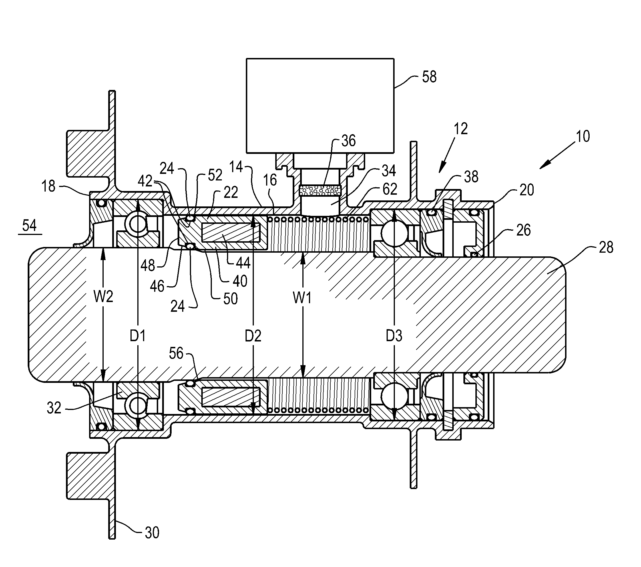
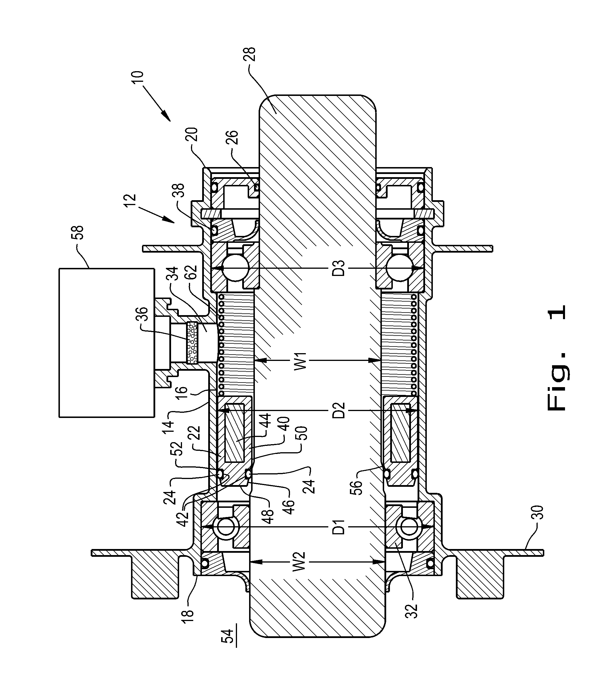
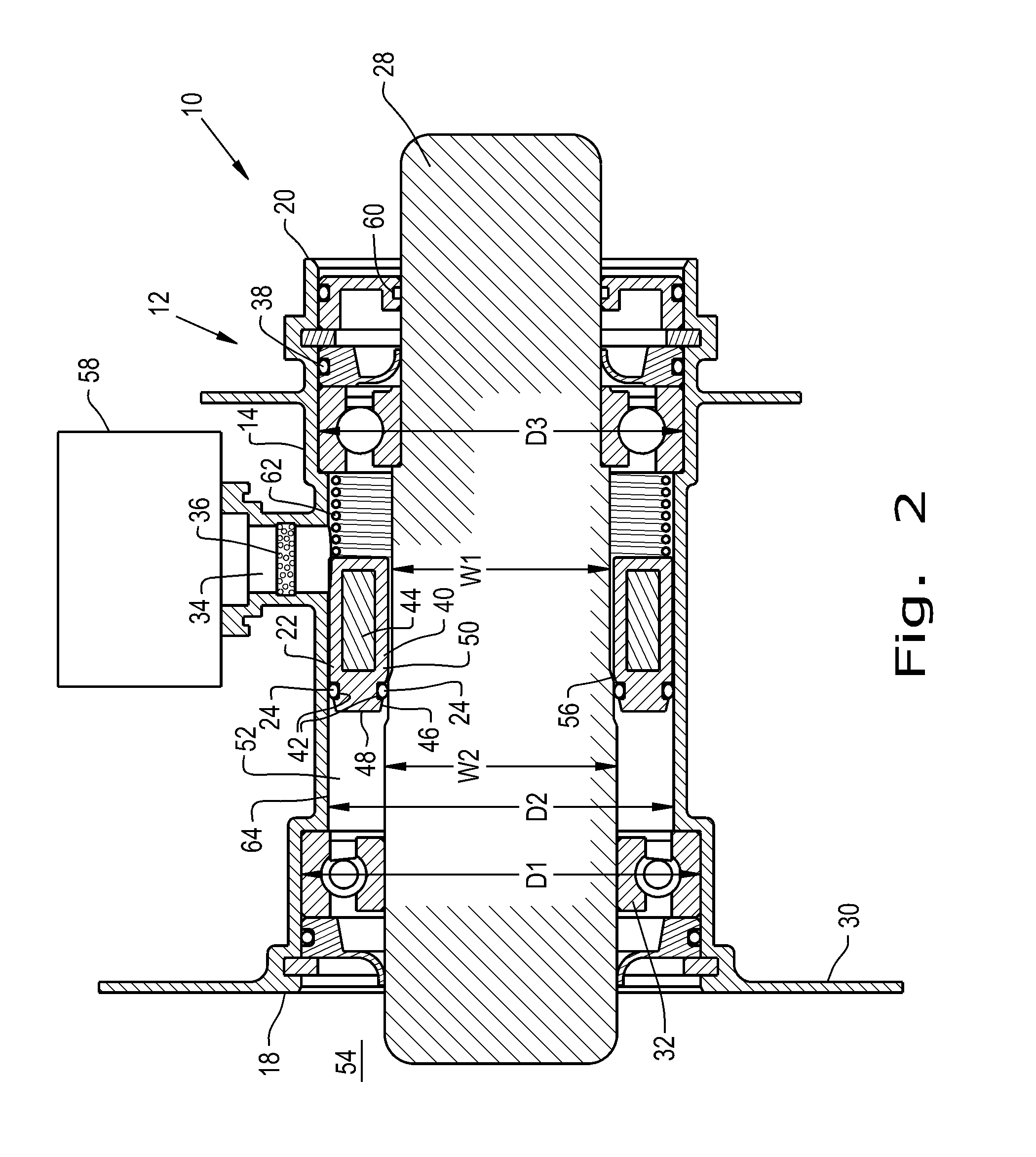
[0024]Referring now to the drawings, and more particularly to FIG. 1, there is shown an embodiment of an agitating assembly 10 formed according to the present invention including a seal assembly 12 for a sterile environment which generally includes a seal body 14 with a space 16 formed in the seal body 14 from one end 18 of the seal body 14 to an opposite end 20 of the seal body 14, a seal carrier 22 held within the space 16 of the seal body 14 that can be selectively positioned in a sealing position and a rotation position and defines a carrying path, at least one seal 24 carried by the seal carrier 22, and a hermetic seal 26 held within the space 16 of the seal body 14 out of the carrying path of the seal carrier 22. The seal assembly 12, which can be referred to as a “pass-through,” can be placed on a shaft 28 so the shaft 28 is inserted through the space 16 of the seal body 14, with the seal(s) 24 and hermetic seal 26 sealing around the shaft 28, which will be described further ...


PUM


Abstract

A seal assembly includes a seal body having a space formed therein; a seal carrier held within the space, the seal carrier being selectively positionable between a sealing position and a rotation position by moving along a carrying path; at least one seal carried by the seal carrier; and a hermetic seal held within the space out of the carrying path of the seal carrier, the hermetic seal being configured to be abraded away by a rotating element that the hermetic seal is pressing against.

Description

CROSS REFERENCE TO RELATED APPLICATIONS[0001]This is a non-provisional application based upon U.S. provisional patent application Ser. No. 62 / 156,525, entitled “SEAL ASSEMBLY FOR A STERILE ENVIRONMENT”, filed May 4, 2015, which is incorporated herein by reference.BACKGROUND OF THE INVENTION[0002]1. Field of the Invention[0003]The present invention relates to seals, and, more particularly, to seals for maintaining a sterile environment.[0004]2. Description of the Related Art[0005]Certain products, especially those in the pharmaceutical and food industries, require high degrees of sterility in the manufacturing process so the products are safe for users to consume. Manufacturing such products typically occurs in designated “clean rooms” where the environment and equipment is strictly controlled to prevent the introduction of foreign organisms and debris into the products during the manufacturing process. Maintaining the sterility in cleans rooms can be achieved by a combination of ind...

Claims


Application Information

Patent Timeline
Patent Type & Authority Applications(United States)
IPC IPC(8): F16J15/00B01F15/00F16J15/40F16J15/3252F16J15/3268
CPCF16J15/002F16J15/3252F16J15/3268B01F2015/00097B01F15/00435B01F2015/00084F16J15/40F16J15/008F16C33/76B01F27/00B01F2035/3512
Inventor MILLER, TIMOTHY F.BERG, CHRISTOPHER
Owner TRELLEBORG SEALING SOLUTIONS GERMANY
Why Eureka
Try Eureka