Belt type fixing apparatus and image forming apparatus comprising same

a technology of fixing apparatus and fixing belt, which is applied in the direction of electrographic process apparatus, instruments, optics, etc., can solve the problem of short life-span of the fixing belt, and achieve the effect of minimizing fatigue cracks and increasing life-span

Active Publication Date: 2016-11-10
HEWLETT PACKARD DEV CO LP
View PDF4 Cites 30 Cited by
  • Summary
  • Abstract
  • Description
  • Claims
  • Application Information

AI Technical Summary

Benefits of technology

[0007]The present disclosure has been developed in order to overcome the above drawbacks and other problems associated with the conventional arrangement. An aspec

Problems solved by technology

However, since fatigue cracks occur at opposite ends of the fixing belt due to repetitive rotation of th

Method used


Image

  • Belt type fixing apparatus and image forming apparatus comprising same
  • Belt type fixing apparatus and image forming apparatus comprising same
  • Belt type fixing apparatus and image forming apparatus comprising same

Examples


Embodiment Construction

[0057]Hereinafter, certain exemplary embodiments of the present disclosure will be described in detail with reference to the accompanying drawings.

[0058]The matters defined herein, such as a detailed construction and elements thereof, are provided to assist in a comprehensive understanding of this description. Thus, it is apparent that exemplary embodiments may be carried out without those defined matters. Also, well-known functions or constructions are omitted to provide a clear and concise description of exemplary embodiments. Further, dimensions of various elements in the accompanying drawings may be arbitrarily increased or decreased for assisting in a comprehensive understanding.

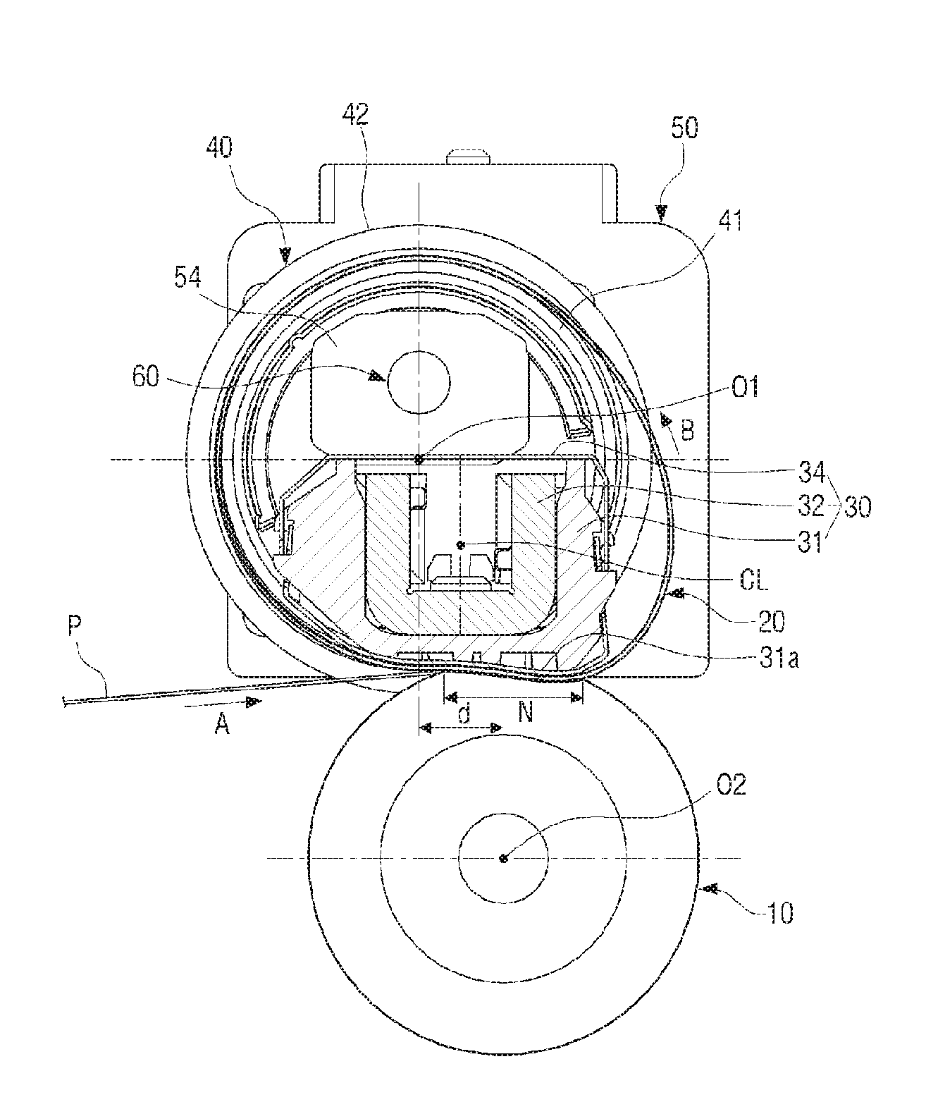
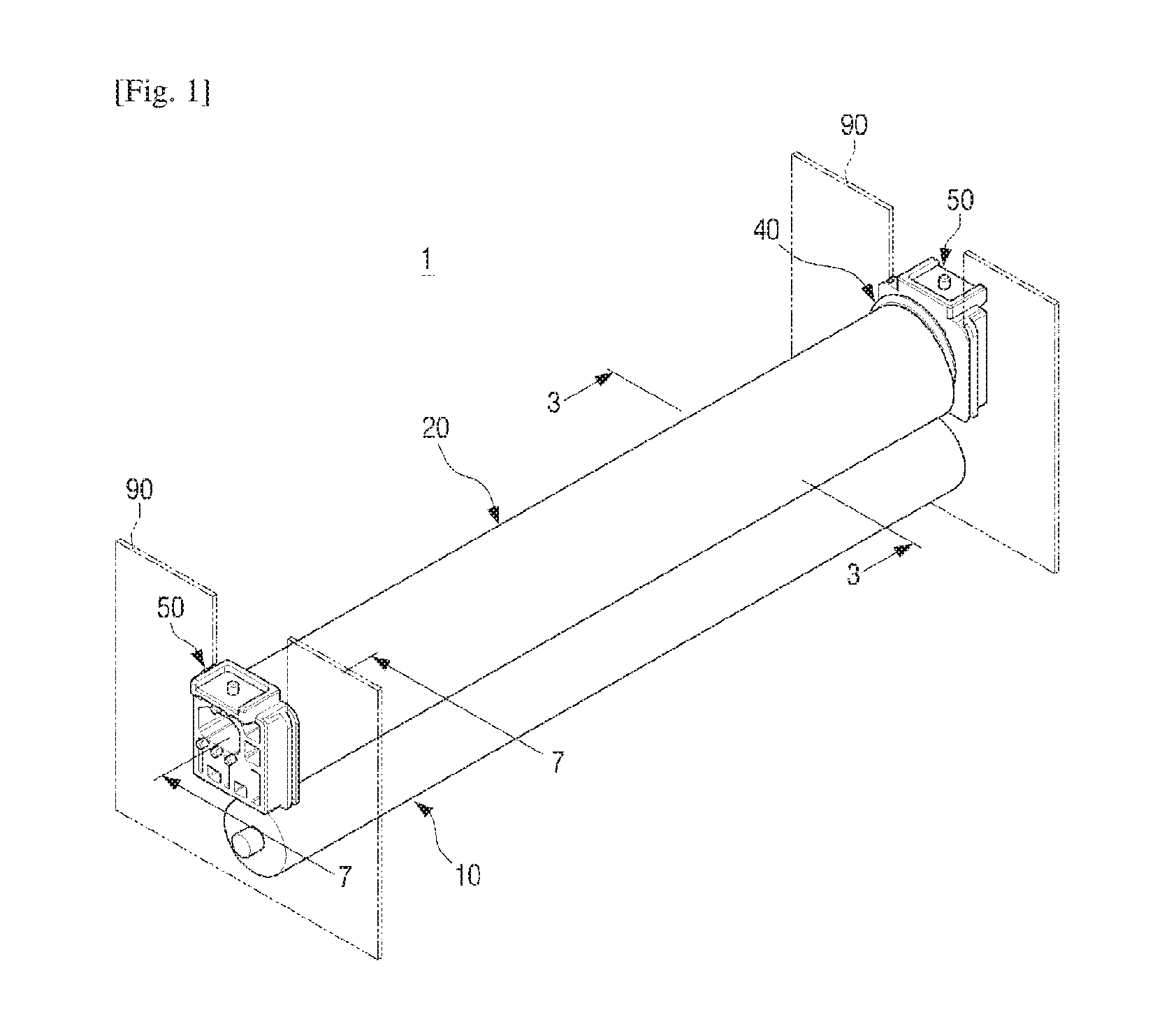
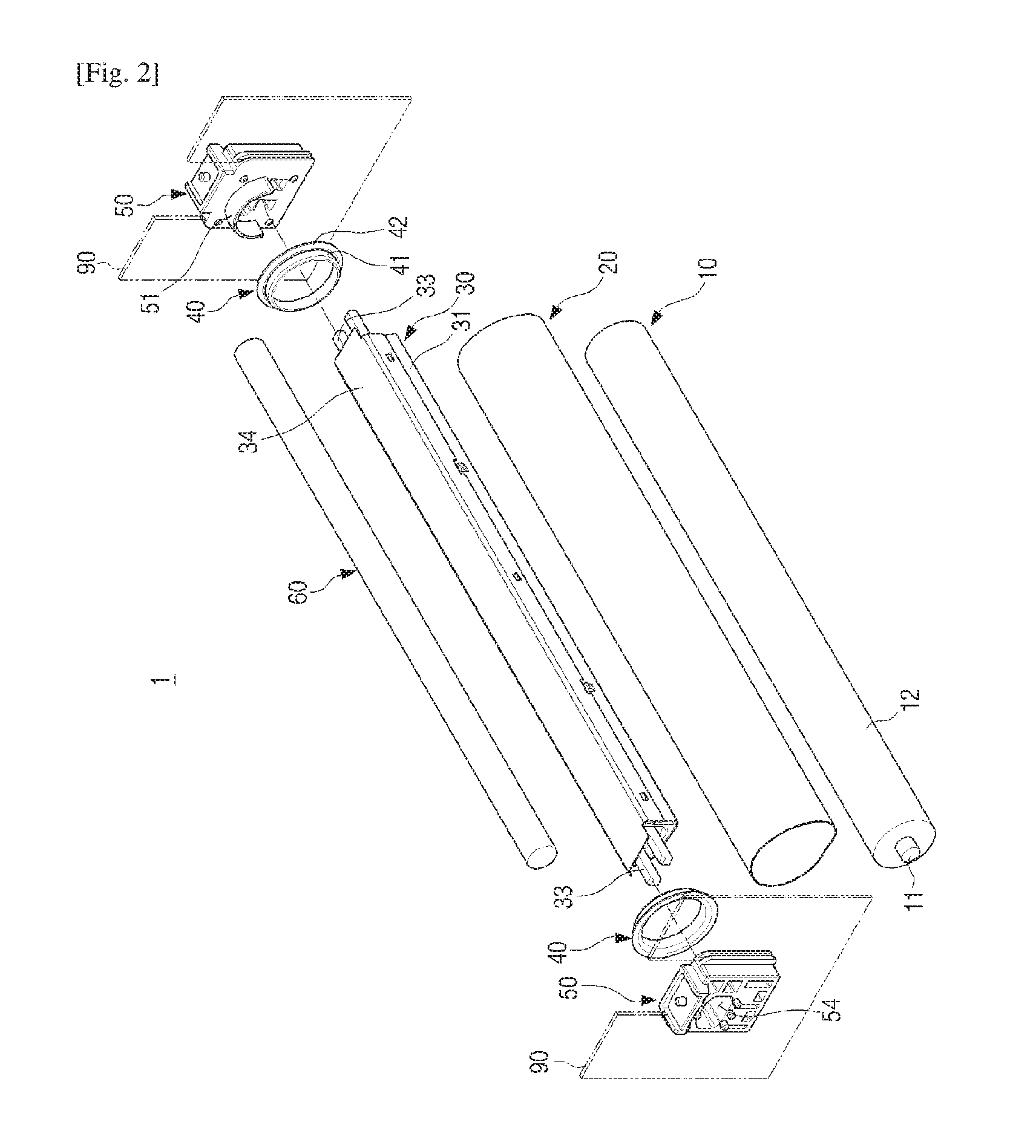
[0059]FIG. 1 is a perspective view schematically illustrating a belt type fixing apparatus 1 according to an embodiment of the present disclosure, and FIG. 2 is an exploded perspective view illustrating the belt type fixing apparatus 1 of FIG. 1. FIG. 3 is a cross-sectional view illustrating the belt ty...


PUM


Abstract

A belt type fixing apparatus comprises: a fixing roller; a fixing belt which is installed to be opposite to the fixing roller;
a nip forming member which is installed inside the fixing belt and supports the fixing belt so that the fixing belt can contact the fixing roller to form a fixing nip; a pair of sliding members which are installed to support both ends of the fixing belt and are rotated by the fixing belt; a pair of flange members which rotatably support the pair of sliding members; and a heat source which is installed inside the fixing belt and generates heat, wherein the rotation center of the pair of sliding members is located upstream in the transportation direction of printed matter compared to the rotation center of the fixing roller.

Description

TECHNICAL FIELD[0001]The present disclosure relates to an image forming apparatus. More particularly, the present disclosure relates to a fixing apparatus configured to fix an image onto a print medium.BACKGROUND ART[0002]Generally, an electro-photographic image forming apparatus such as a laser printer forms a developer image corresponding to a certain image on a print medium, and uses a fixing apparatus that permanently fixes the developer image onto the print medium by applying heat and pressure to the developer image[0003]The fixing apparatus includes a pair of rollers, namely, a heat roller configured to generate heat to be applied to the print medium and a fixing roller configured to apply a predetermined pressure to the print medium.[0004]However, these days, image forming apparatuses for high-speed printing have widely used a fixing apparatus configured to use a fixing belt of an endless belt instead of a heat roller.[0005]However, since fatigue cracks occur at opposite ends...

Claims


Application Information

Patent Timeline
IPC IPC(8): G03G15/20
CPCG03G15/2085G03G15/2053G03G2215/2025G03G15/2064G03G2215/2035G03G15/2028
Inventor KIM, JUN-TAELEE, SEUNG-JUNLEE, DONG-WOOSEOL, DONG-JINBAE, SOO-HWANLEE, BONG-HEE
Owner HEWLETT PACKARD DEV CO LP
Why Eureka
Try Eureka