
Cartilage holding forceps

a tissue holding and forcep technology, applied in the field of tissue holding forceps, can solve the problems of crushing soft tissues, slipping, and affecting the operation, so as to facilitate stitching and other surgical operations, reduce the time of operation, and fast and easy surgical operations

Active Publication Date: 2016-11-17
FAROOQ MUHAMMAD
View PDF9 Cites 2 Cited by
  • Summary
  • Abstract
  • Description
  • Claims
  • Application Information

AI Technical Summary

Benefits of technology

This patent is about a new design of forceps used in medical surgery. The forceps have two arms with jaws at the head that can grip tissue tightly. The forceps also have a sharp cutting edge in the center that helps with surgical procedures. The design of the forceps is unique and makes surgical procedures faster and easier.

Problems solved by technology

Such conventional forceps cause a considerable amount of crushing of tissues, leaving behind visible marks on the tissue.
However, conventional forceps have problems of slipping, crushing soft tissues; and do not have friendly design for easy and fast stitching during surgical operations.

Method used


Image

  • Cartilage holding forceps
  • Cartilage holding forceps
  • Cartilage holding forceps

Examples


example no.1

Example No. 1

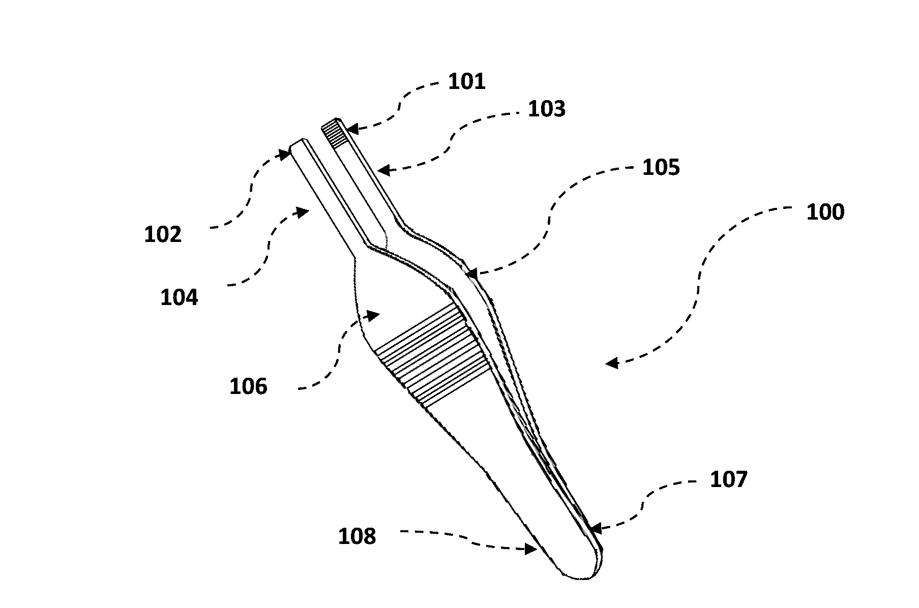
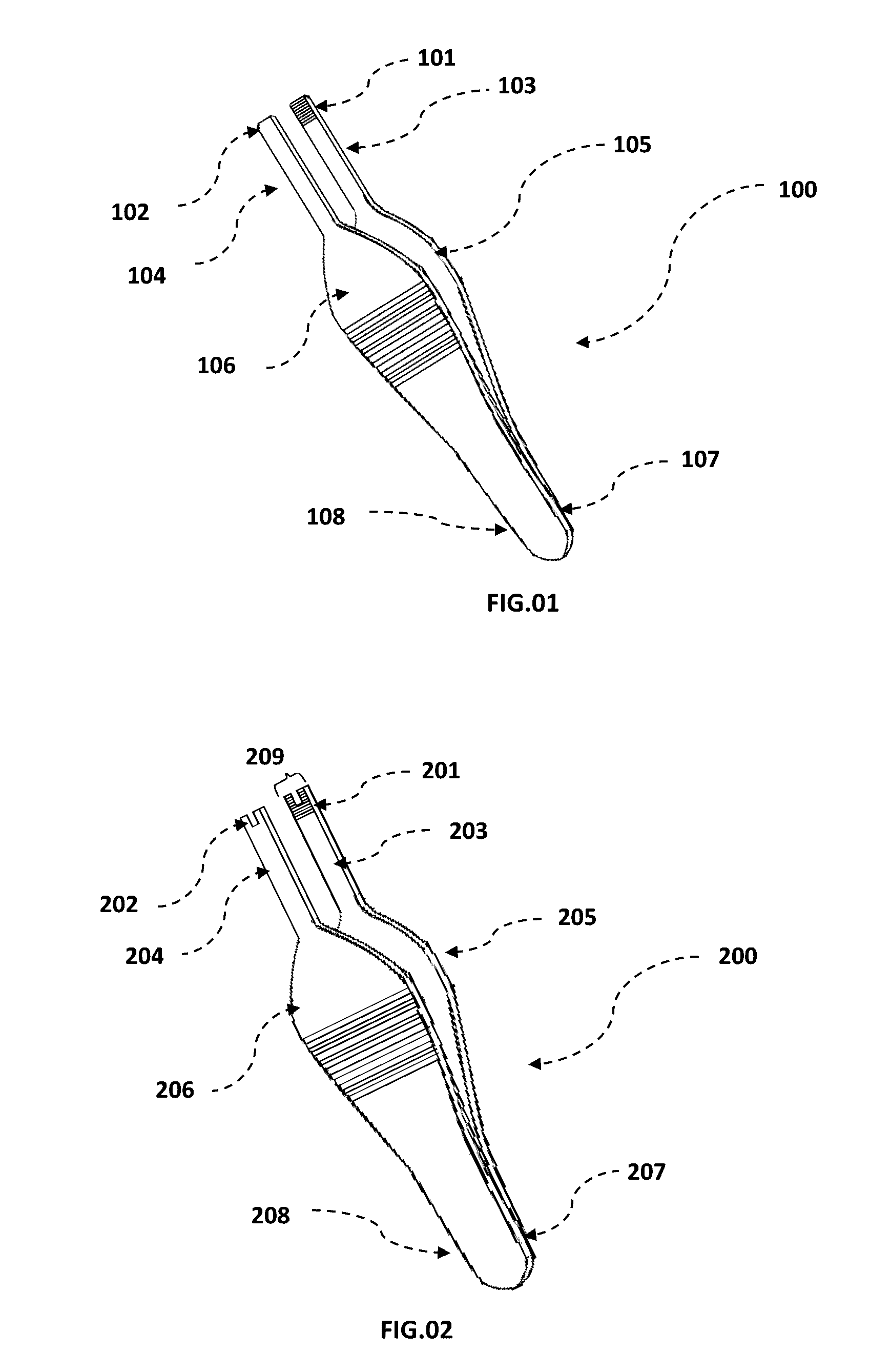
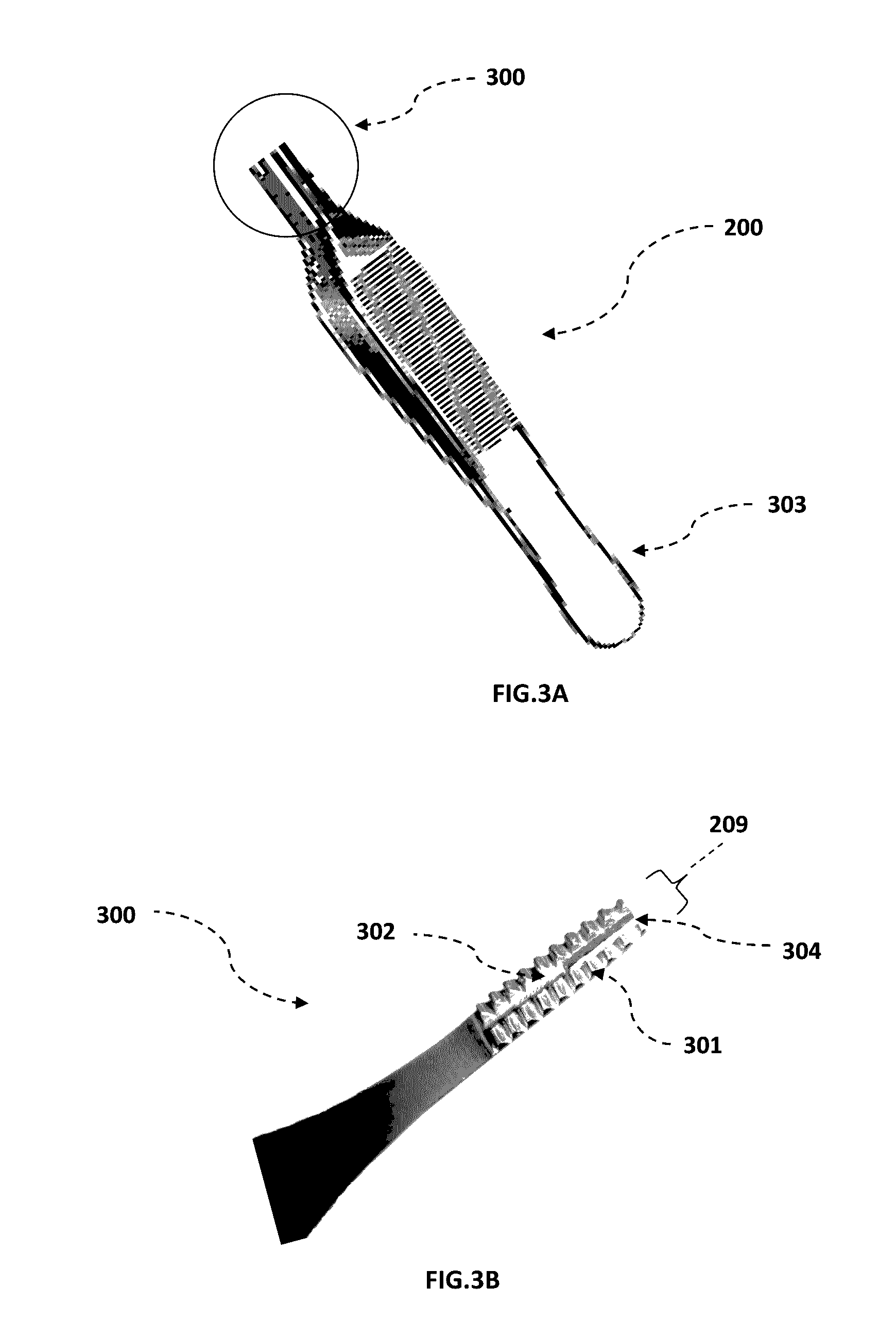
[0034]A novel design of Forceps is constructed by titanium where the shape of the Forceps is like Adson- Brown forceps but with modifications of central cut in the jaw tip of the Forceps where the width of central cut is 0.7 mm and depth is 12 mm from head towards rear end of each arm of the Forceps. There are two rows of sharp elongated teeth at jaws of each arm of Forceps to support firm grip of tissue which also extends beyond to central cut. There is also a deep groove in the mid of jaw of each arm of the Forceps to support flow of extra waste fluids like blood during operation.

example no.2

Example No. 2

[0035]A novel design of Forceps is constructed by Tungsten Carbide where the shape of the Forceps is like Adson-Brown Tungsten Carbide Forceps but with modifications of central cut in the jaw tip of the Forceps where the width of central cut is 0.6 mm and depth is 10 mm from head towards rear end of each arm of the Forceps. There are two rows of fine pyramidal shaped sharp teeth somewhat similar to file tool at jaws of each arm of Forceps to support firm grip of tissue which also extends beyond to central cut. There is also a deep groove in the mid of jaw of each arm of the Forceps to support flow of extra waste fluids like blood during operation.

example no.3

Example No. 3

[0036]A novel design of Forceps is constructed by stainless steel where the shape of the Forceps is like adjustable scissor shaped Forceps but with modifications of central cut in the jaw tip of the Forceps where the width of central cut is 0.8 mm and depth is 11 mm from head towards rear end of each arm of the Forceps. There are four rows of linear fine sharp teeth at jaws of each arm of Forceps to support firm grip of tissue which also extends beyond to central cut. There is also a deep groove in the mid of jaw of each arm of the Forceps to support flow of extra waste fluids like blood during operation.


PUM


Abstract

This invention is an advanced tissue gripping forceps with novel design of forcep's jaw best suitable for medical surgery. The novel tissue holding forceps has first and second arms with two ends each i.e Head and rear end; and jaws at the heads of each arms of the forceps. The rear ends of two arms of the forceps are coupled together. The second ends, the head of the First and Second arms of the forceps form opposing First and second jaws which are resiliently biased apart. The First and second jaws each include a plurality of sharp, directly opposing sharp elongated teeth to grip the tissue firmly during the use. The both jaws has a deep “CUT” in the center which makes jaw as “U” shape. This novel design enable fast and easy surgical operations by reducing the time of operation by facilitating the stitching and other surgical operations.

Description

TECHNICAL FIELD OF INVENTION[0001]The present invention discloses a novel design of tissue holding forceps generally used in the medical surgery. Tissue forceps are used for grasping tissues during surgical operations which do not squeeze or crush soft tissue such as skin during use.BACKGROUND ART[0002]Tissue Forceps are devices used by doctors and medical practitioners to grip the soft tissue such as skin during surgery or other medical procedures. Traditionally, forceps have been available in a number of different type and designs like hemostatic forceps, tissue forceps, Kelly forceps, and biopsy forceps. Conventional forceps have two grasping jaws at the top end thereof which can be plain or smooth, finely serrated so that they will not slip during grasping, or with interdigitating sharp elongated teeth. Such conventional forceps cause a considerable amount of crushing of tissues, leaving behind visible marks on the tissue.[0003]The commonly known forceps design used by plastic s...

Claims


Application Information

Patent Timeline
Patent Type & Authority Applications(United States)
IPC IPC(8): A61B17/28A61B17/30
CPCA61B17/282A61B2017/2837A61B17/30A61B17/2833A61B17/0483
Inventor MOHMAND, MUHAMMAD HUMAYUN
Owner FAROOQ MUHAMMAD
Learn More