Heat shield for mixed flow turbine wheel turbochargers

a turbine wheel and heat shield technology, which is applied in the direction of machines/engines, stators, mechanical equipment, etc., can solve the problems of shield shape and turbine efficiency affecting the efficiency of the turbine, delay before the turbocharger boost is actually provided to the engine, etc., to improve the efficiency of the turbocharger, and improve the gas flow of the compressor

Active Publication Date: 2016-11-24
BORGWARNER INC
View PDF23 Cites 8 Cited by
  • Summary
  • Abstract
  • Description
  • Claims
  • Application Information

AI Technical Summary

Benefits of technology

[0011]A variable turbine geometry turbocharger has a mixed flow turbine wheel, guide vanes, and a heat shield. In some embodiments, a front edge of the heat shield is contoured such that a slope of the contour defines an imaginary line that if extended would meet the axis of rotation of the turbocharger shaft at an angle of about 40 to 50 degrees. Exhaust gas flowing from the turbine housing is directed along the extended imaginary line defined by the slope of the contour and into the blade passage, directly between the hub and the shroud (e.g., an inner surface of the turbine housing). The contour is in the form of a chamfer, and can also be in the shape of a convex or concave curve. Further, the heat shield includes relatively short sides that prevent the heat shield from being positioned in the direct stream of exhaust gas flowing to the turbine. The turbocharger including the contoured heat shield provides greater compressor gas flow than a turbocharger of conventional construction wherein the heat shield is disposed in the direct stream of exhaust gas and wherein the heat shield does not have a front edge contour that aids in directing the flow of exhaust gas directly onto the blade passage. Thus, the heat shield is configured to provide improved turbocharger efficiency relative to some turbochargers including a conventional heat shield. The increased efficiency of the turbocharger is greatest at low vane openings, which leads to a reduction in turbolag.

Problems solved by technology

At low speeds there is often a delay before turbocharger boost is actually provided to the engine.
However, due to the position of the heat shield with respect to the gas flow path through the turbocharger, the heat shield shape can affect turbine efficiency.

Method used


Image

  • Heat shield for mixed flow turbine wheel turbochargers
  • Heat shield for mixed flow turbine wheel turbochargers
  • Heat shield for mixed flow turbine wheel turbochargers

Examples


example 1

EXAMPLE 1

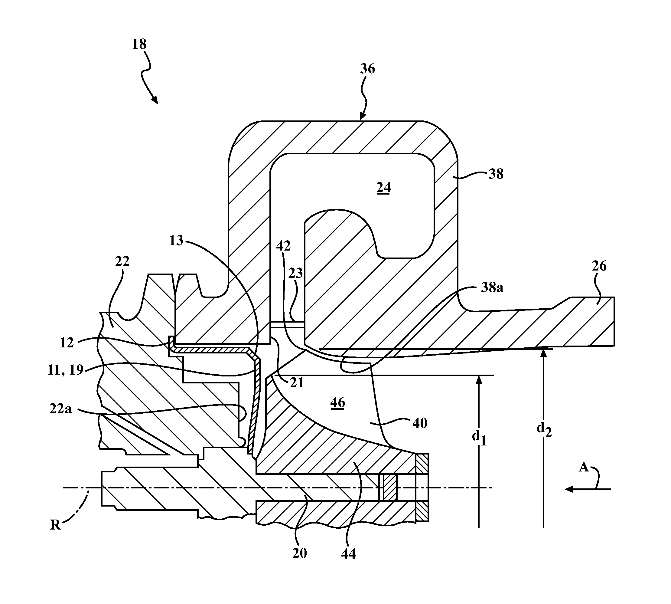
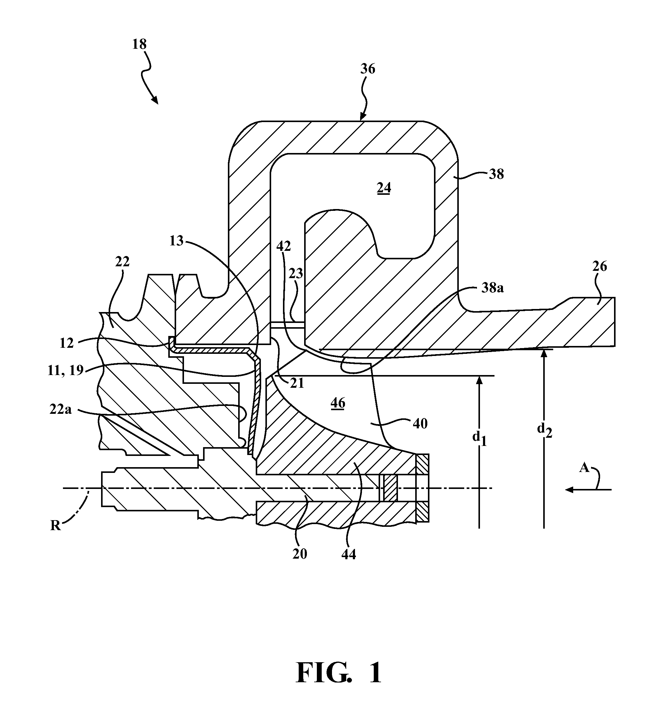
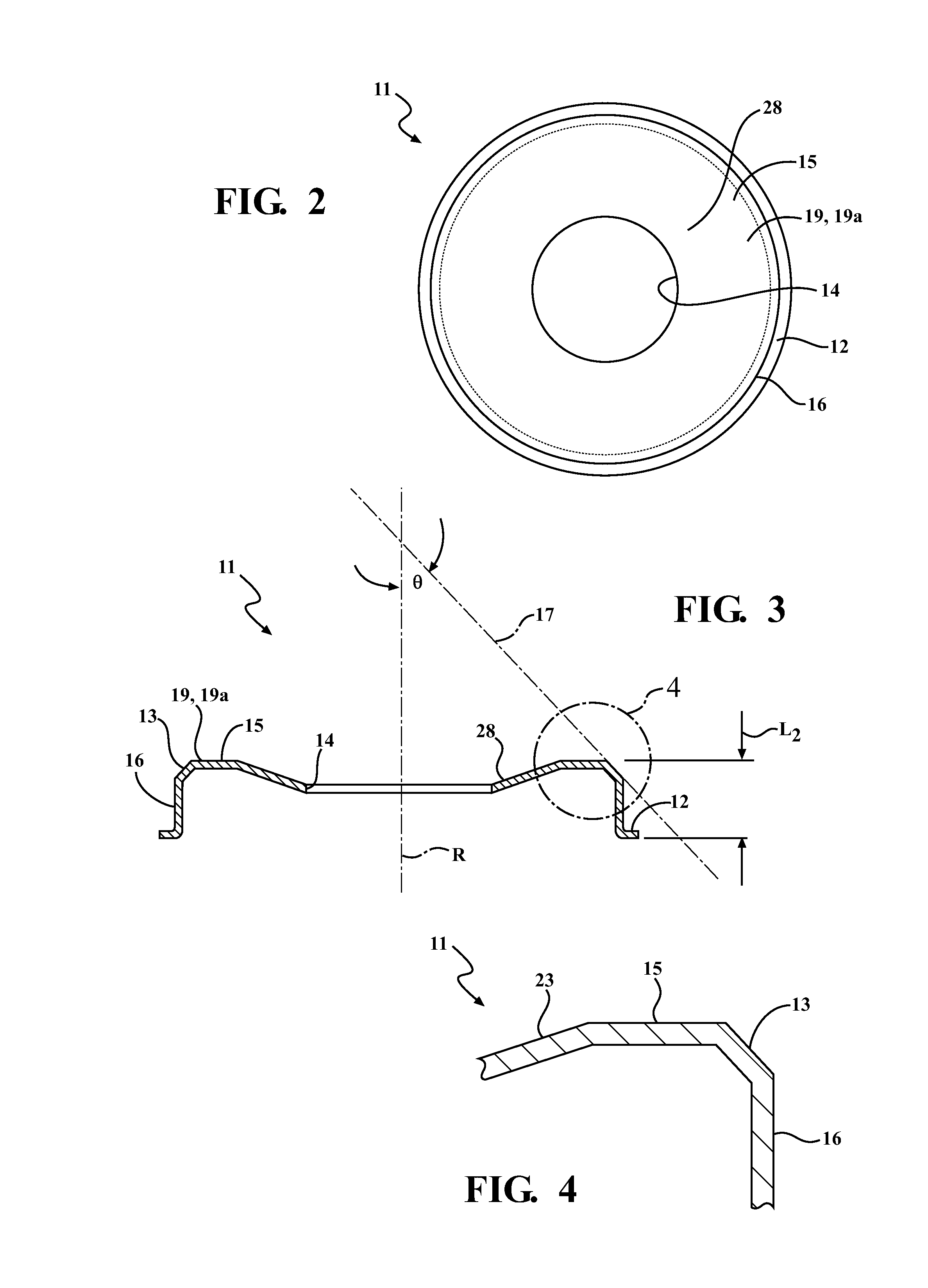
[0037]A variable turbine geometry turbocharger having a mixed flow turbine and variable vanes was constructed. A conventional heat shield 1 was prepared having a 2 mm retaining tab, thus the conventional heat shield 1 had a total diameter of 67 mm. In addition, the front edge of the conventional heat shield 1 defined a sharp corner. In use within the turbocharger, the sharp corner was positioned within the gas stream. In addition, a mixed flow heat shield 11 according to the embodiment shown in FIGS. 1-4 was prepared. The heat shield 11 was 63 mm in diameter with a 2 mm retaining tab and a total diameter of 67 mm. The front edge 13 had a chamfered edge with a length of approximately 3 mm. The line defined by the chamfer made an angle of 42.3 degrees with the turbocharger shaft. The heat shield 11 had a sidewall length L2 that was shorter than the sidewall length L1 of the conventional heat shield 1. Thus, in use, the heat shield 11 was positioned behind (e.g., axially inwar...


PUM


Abstract

A turbocharger (18) includes a shaft (20), a mixed flow turbine wheel (40) including a wheel hub (44) and blades having tips (42), and a heat shield (11). The heat shield (11) has a side wall, an end (19), and a contoured front edge (13) that connects the sidewall (16) and the end (19). The front edge (13) of the heat shield (11) defines a slope that forms an imaginary line that is angled relative to the sidewall (16) and the end (19), and intersects an axis of rotation of the shaft (20). The heat shield (11) resides at a position that is between a bearing housing (22) of the turbocharger (18) and the turbine wheel (40), and axially inward relative to an axially-facing surface of a turbine volute (24), and between the bearing housing (22) and the turbine wheel (40).

Description

CROSS-REFERENCE TO RELATED APPLICATION[0001]This application claims priority to and all the benefits of U.S. Provisional Application No. 61 / 935,466, filed on Feb. 4, 2014, and entitled “Heat Shield For Mixed Flow Turbine Wheel Turbochargers,” which is incorporated herein by reference.BACKGROUND OF THE INVENTION[0002]1. Field of the Invention[0003]This disclosure relates to an exhaust gas turbocharger for an internal combustion engine. More particularly, this disclosure relates to a heat shield for a variable turbine geometry turbocharger having a mixed flow turbine wheel.[0004]2. Description of Related Art[0005]A turbocharger is a type of forced induction system used with internal combustion engines. Turbochargers deliver compressed air to an engine intake, allowing more fuel to be combusted, thus boosting the horsepower of the engine without significantly increasing engine weight. Thus, turbochargers permit the use of smaller engines that develop the same amount of horsepower as la...

Claims


Application Information

Patent Timeline
Patent Type & Authority Applications(United States)
IPC IPC(8): F01D25/14F01D25/26F01D17/14F01D5/04F01D9/04F02B37/24F01D25/12
CPCF01D25/145F02B37/24F01D25/26F01D25/125F01D5/04F05D2260/231F01D17/14F05D2220/40F05D2240/24F05D2240/60F05D2240/54F01D9/041F02C7/24F05D2250/192F05D2250/314F05D2250/711F05D2250/712Y02T10/12
Inventor CHANDRAMOHANAN, RAJMOHAN T.WILLIAMS, GREG
Owner BORGWARNER INC
Why Eureka
Try Eureka