
Reinforced end cap assembly for pressure vessel

a technology of end caps and pressure vessels, which is applied in the direction of fluid pressure injection control, fuel injection apparatus, feed system, etc., can solve the problems of insufficient use of stamping metal end caps, limited maximum thickness of metal stock that can be stamped into end caps, and inability to stamp wall thickness, etc., to achieve cost reduction and cost saving effect of end cap assemblies

Inactive Publication Date: 2016-11-24
MILLENNIUM INDS
View PDF0 Cites 5 Cited by
  • Summary
  • Abstract
  • Description
  • Claims
  • Application Information

AI Technical Summary

Benefits of technology

The present teachings describe an end cap assembly for high pressure applications that is cost-effective compared to conventional configurations. The assembly includes a cup and a reinforcement that is directly mounted to the interior of the cup using a brazing material. The reinforcement increases the wall thickness of an exposed area of the cup. In one embodiment, the cost savings for the end cap assembly is as much as 40% compared to a machined end cap assembly. The technical benefits of this design are improved durability and performance in high pressure applications.

Problems solved by technology

However, the above-mentioned stamped metal end caps are not used in such higher pressure systems because of limitations in the stamping wall thickness.
In other words, there is a practical limit in the maximum thickness of the metal stock that can be stamped into an end cap.
This (limited) thickness end cap is not suitable for such higher pressures.
And while a machined metal end cap can be used that has the needed wall thickness for the increased fuel pressures, the machined end cap is more expensive.
In addition, the gap left by the tube counter-bore that is not filled by the cap creates a stress riser for fatigue failures.

Method used


Image

  • Reinforced end cap assembly for pressure vessel
  • Reinforced end cap assembly for pressure vessel
  • Reinforced end cap assembly for pressure vessel

Examples


first embodiment

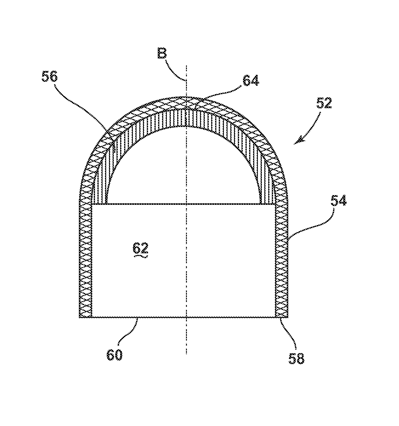
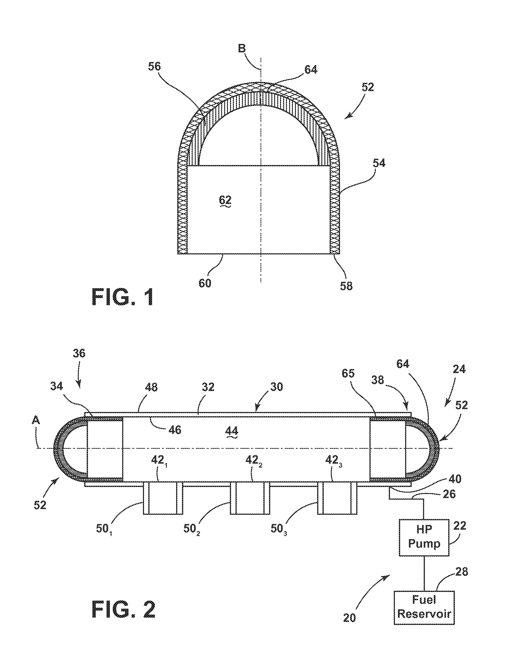
[0029]Referring now to Figures wherein like reference numerals identify identical or similar components in the various views, FIG. 1 is a simplified cross-sectional view of a first end cap assembly in accordance with the instant disclosure, while FIG. 2 is a cross-sectional view of a fuel rail assembly that employs the end cap assembly shown in FIG. 1. As shown, the cross-section of the fuel rail assembly of FIG. 2 is taken substantially along the longitudinal axis of the fluid conduit. The fluid (e.g., fuel) delivery system and the components and methods of assembling the same to be described herein may have application with respect to a spark-ignited, fuel-injected internal combustion engine; however, other applications are contemplated, as will be recognized by one of ordinary skill in the art.

[0030]With continued reference to FIGS. 1 and 2, a fuel delivery system 20 includes a high-pressure fuel source such as a fuel pump 22, a fuel rail assembly 24, and a supply hose or conduit...

second embodiment

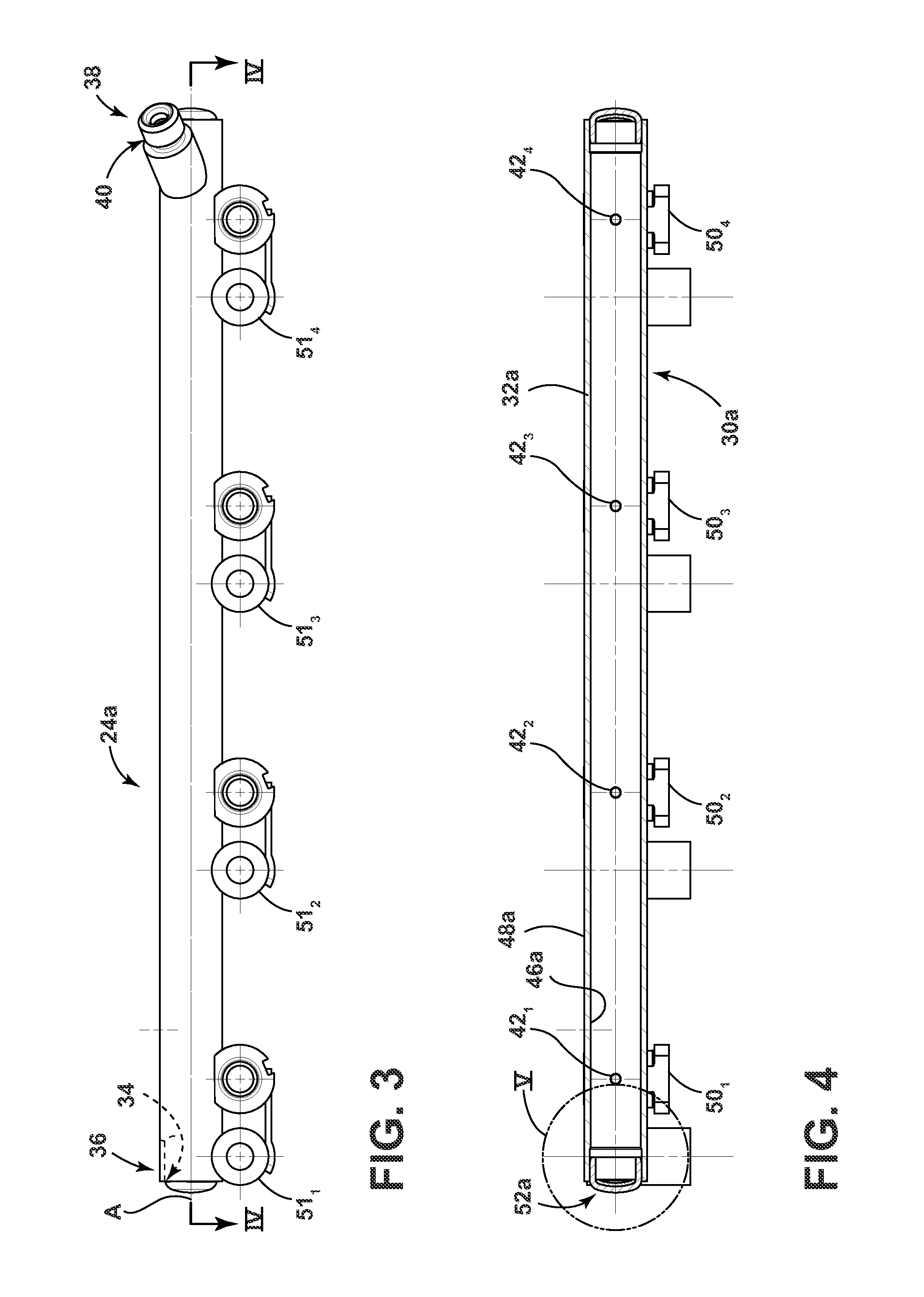
[0043]FIGS. 3-5 illustrate a fuel rail assembly 24a that uses an end cap assembly, designated end cap assembly 52a. Features and / or components of this embodiment that are similar to corresponding features and / or components in the previously-described embodiment append an “a” suffix to the pertinent reference numeral. Additionally, the description of the fuel rail assembly 24 and the end cap assembly 52 made above applies generally to the fuel rail assembly 24a and the end cap assembly 52a, with the following additional description(s).

[0044]Referring now to FIG. 5, the end cap assembly 52a includes a cup 54a and a reinforcement 56a. The cup 54a includes a base 76a and an annular sidewall 78a axially extending away from the base 76a. The annular sidewall 78a has a free edge 58a that defines an aperture 60a that leads to an interior 62a of the cup 54a. The cup 54a has inner surfaces 64a (corresponding to the base) and 82a (corresponding to the annular sidewall) that face the interior 6...

third embodiment

[0049]FIGS. 6-8 illustrate a fuel rail assembly 24b that includes an end cap assembly, designated end cap assembly 52b. Features and / or components in this embodiments that are similar to the corresponding features and / or components in the previously-described embodiments append a “b” suffix to the pertinent reference numeral. Additionally, the description of the fuel rail assemblies 24, 24a and the end cap assemblies 52, 52a made above applies generally to the fuel rail assembly 24b and the end cap assembly 52b, with the following additional description(s).

[0050]Referring now to FIG. 8, the end cap assembly 52b includes a cup 54b and an annular reinforcement 56b. The cup 54b is generally annular and includes a base 76b and an annular sidewall 78b axially extending away from the base 76b. The annular sidewall 78b has a free edge 58b that defines an aperture 60b that leads to an interior 62b of the cup 54b. The cup 54b has inner surfaces 64b, 82b that face the interior 62b. In this em...


PUM


Abstract

A fuel rail or pressure vessel assembly extends along a longitudinal axis and includes a fluid conduit having an opening at either or both of the longitudinal ends of the conduit. The conduit has an inlet coupled to a high-pressure fuel source, a plurality of outlets, and a conduit interior that forms a fluid flow passageway between inlet and outlets. An end cap assembly is mounted to cover and close each fluid conduit opening. The end cap assembly includes a cup having a free edge that defines an aperture that leads to a cup interior. The cup has an inner surface facing the conduit interior. The end cap assembly also includes a reinforcement that is mounted to the inner surface of the cup. Both the cup and the reinforcement can be stamped metal components and are brazed together.

Description

CROSS-REFERENCE TO RELATED APPLICATIONS[0001]Not applicable.BACKGROUND[0002]a. Technical Field[0003]The instant disclosure relates generally to a fuel rail assembly and more specifically to an end cap assembly for the fuel rail assembly.[0004]b. Background Art[0005]This background description is set forth below for the purpose of providing context only. Therefore, any aspects of this background description, to the extent that it does not otherwise qualify as prior art, is neither expressly nor impliedly admitted as prior art against the instant disclosure.[0006]It is known to provide a fuel delivery system for use with an internal combustion engine. Such a system may include one or more fluid conduits that allow for the delivery of pressurized fuel to multiple fuel injectors. The fluid conduit (i.e., a fuel rail assembly) may include an inlet that is connected to a fuel source, for example, in some systems, an output of a high-pressure fuel pump. The fluid conduit also typically inc...

Claims


Application Information

Patent Timeline
IPC IPC(8): F02M63/02
CPCF02M2200/03F02M2547/005F02M63/0275F02M55/025F02M69/465F02M2200/8084
Inventor ZDROIK, MICHAEL J.
Owner MILLENNIUM INDS
Learn More