
Pixel structure and displaying method thereof, and related display apparatus

a pixel structure and display method technology, applied in the field of display technologies, can solve the problems of difficult to obtain the aperture ratio of the sub-pixels required for providing high resolution, difficult to obtain high resolution, and inability to manufacture amoled display panels, etc., to achieve desirable display brightness, improve the aperture ratio of the sub-pixels, and high resolution

Active Publication Date: 2016-11-24
BOE TECH GRP CO LTD
View PDF38 Cites 39 Cited by
  • Summary
  • Abstract
  • Description
  • Claims
  • Application Information

AI Technical Summary

Benefits of technology

The present invention provides a pixel structure, method, and display apparatus that can achieve high resolution and improve the aperture ratio of sub-pixels to enhance display brightness. This simplifies the manufacturing process and extends the product service time of display panels.

Problems solved by technology

As a result, the manufacturing of AMOLED display panels may be inevitably limited by the opening size of the FMM and precision of the deposition process.
It might be difficult to obtain high resolution.
Particularly, it may difficult to obtain the aperture ratio of the sub-pixels required for providing high resolutions.

Method used


Image

  • Pixel structure and displaying method thereof, and related display apparatus
  • Pixel structure and displaying method thereof, and related display apparatus
  • Pixel structure and displaying method thereof, and related display apparatus

Examples


Embodiment Construction

[0044]For those skilled in the art to better understand the technical solution of the invention, reference will now be made in detail to exemplary embodiments of the invention, which are illustrated in the accompanying drawings. Wherever possible, the same reference numbers will be used throughout the drawings to refer to the same or like parts.

[0045]One aspect of the present disclosure provides a pixel structure.

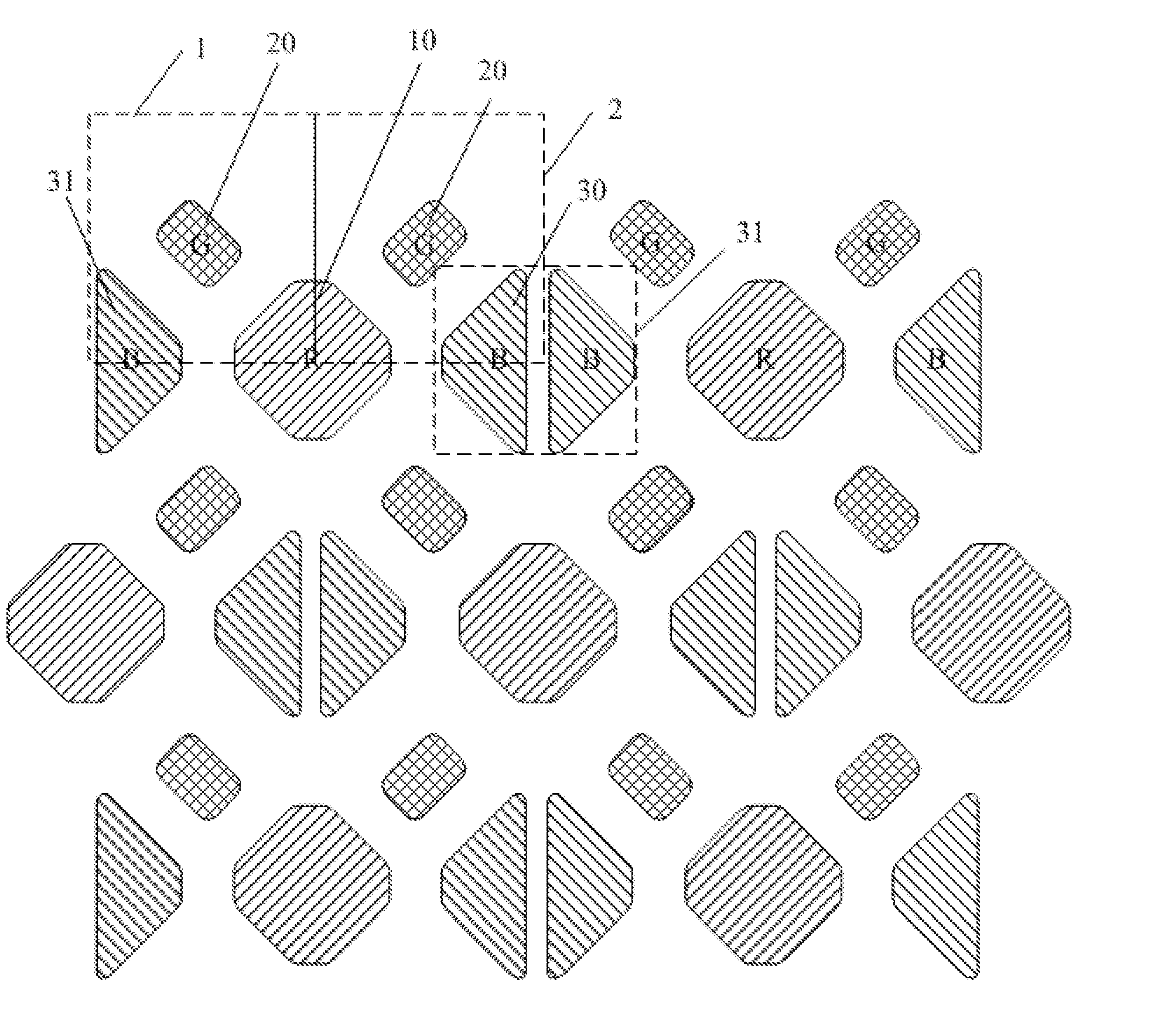
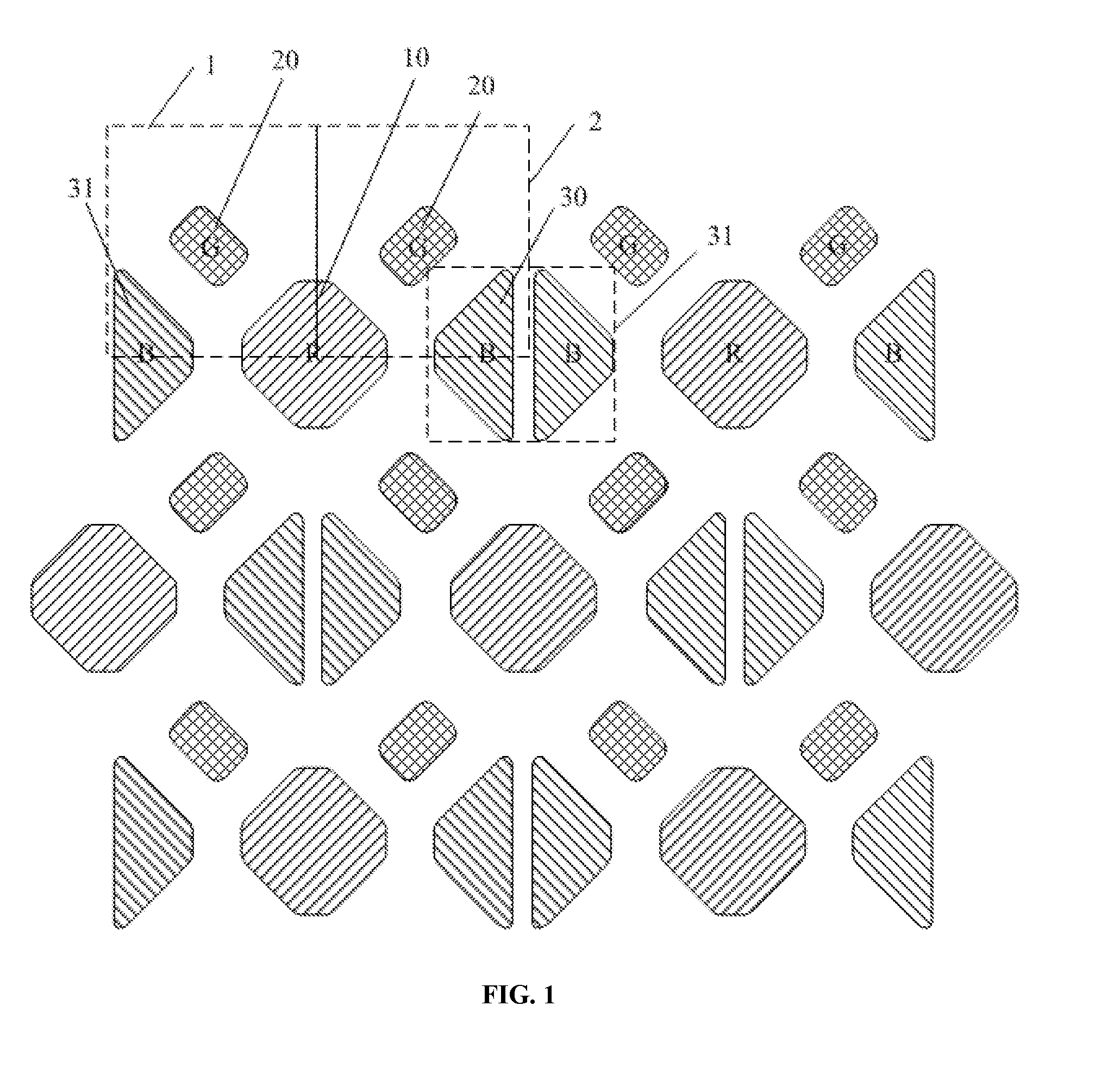
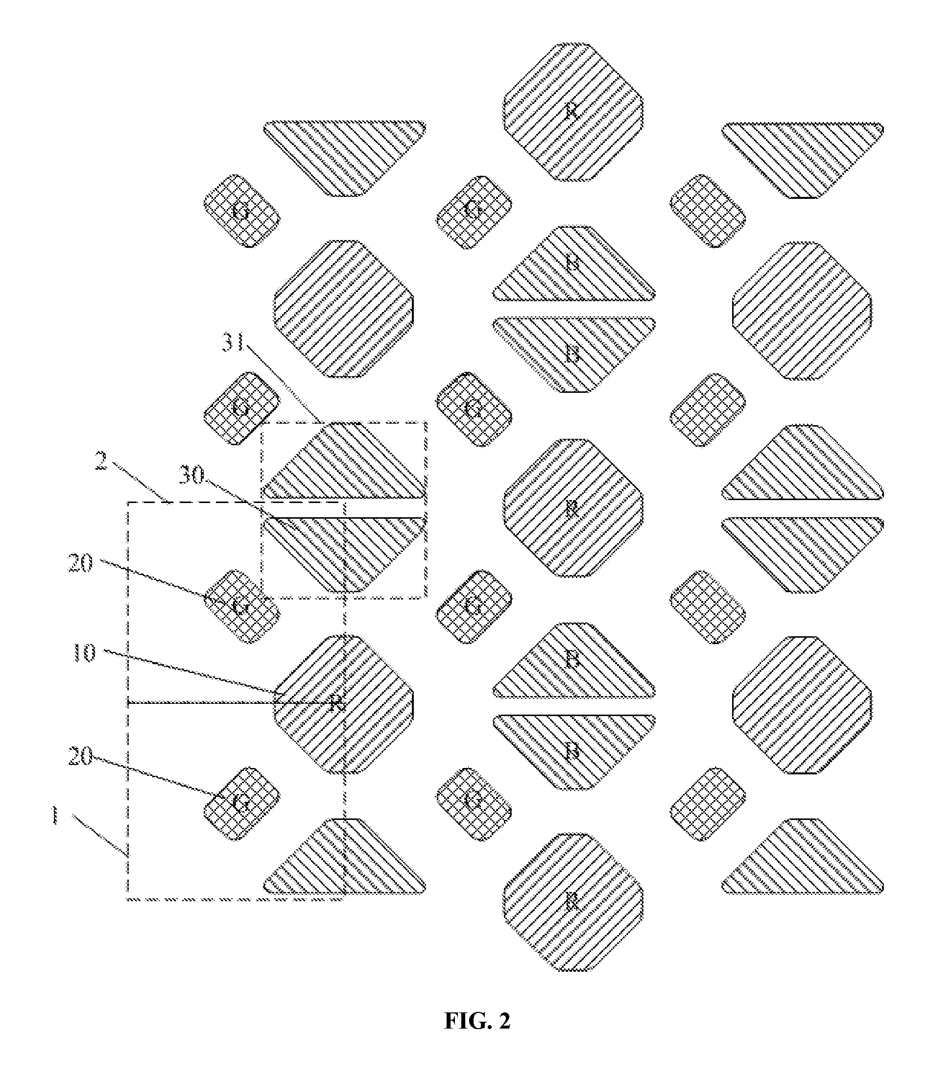
[0046]As shown in FIG. 1, the pixel structure provided in the present disclosure includes first sub-pixels 10, second sub-pixels 20, and third sub-pixels 30. Two opposing adjacent third sub-pixels 30 may be arranged to face each other and form a third sub-pixel group 31. The second sub-pixels 20 may be aligned in a row (e.g., the horizontal direction) to form second-sub-pixel rows. The first sub-pixels 10 and the third sub-pixel groups 31 may be arranged in an alternating configuration in a row, e.g., one first sub-pixel 10 may be arranged between two third sub-pixel groups...


PUM


Abstract

The present disclosure provides a pixel structure. The pixel structure includes first sub-pixels, second sub-pixels, and third sub-pixels. Two adjacent third sub-pixels facing each other form a third sub-pixel group. The second sub-pixels are arranged in a row along a first axis to form second-sub-pixel rows, the first sub-pixels and the third sub-pixel groups are arranged in an alternating configuration along the direction of the first axis parallel to the second-sub-pixel rows, and the second-sub-pixel rows and rows formed by the first sub-pixels and the third sub-pixel groups are arranged in an alternating configuration. The second sub-pixels are arranged along a direction of a second axis to form second-sub-pixel columns, the first sub-pixels and the third sub-pixel groups are arranged in an alternating configuration along the direction of the second axis parallel to the second-sub-pixel columns, the second-sub-pixel columns and columns are arranged in an alternating configuration.

Description

CROSS-REFERENCES TO RELATED APPLICATIONS[0001]This PCT patent application claims priority of Chinese Patent Application No. 201410842321.6, filed on Dec. 30, 2014, the entire content of which is incorporated by reference herein.FIELD OF THE INVENTION[0002]The present invention generally relates to the display technologies and, more particularly, relates to a pixel structure and related displaying method thereof, and a display apparatus containing the same.BACKGROUND[0003]Flat display apparatuses generally include LCD (Liquid Crystal Display) apparatuses and OLED (Organic Light-Emitting Diode) display apparatuses. Particularly, compared to an LCD, an OLED display has advantages such as being self-luminous, having faster response, and providing a wider viewing angle. OLED displays are often suitable for flexible displays, transparent displays, three-dimensional displays, and many other display applications.[0004]Currently, an FMM (Fine Metal Mask) is often applied in the process to ma...

Claims


Application Information

Patent Timeline
IPC IPC(8): G09G3/20G09G3/36G09G3/3225H01L27/32H01L51/00
CPCG09G3/2003H01L27/3218H01L27/3216H01L51/001H01L51/0011G09G3/3225G09G2300/0465G09G3/2074G09G2320/0233G09G2320/043G09G2300/0452G09G2360/147G09G3/3607G02F2201/52H10K59/352H10K59/353G09G3/3208H10K59/131H10K71/164H10K71/166
Inventor SUN, LIANG
Owner BOE TECH GRP CO LTD
Learn More