Magnet terminal with solderless connection structure and jumper wire including the same

a technology of solderless connection and magnet terminal, which is applied in the direction of connection, connection insulation, electrical equipment, etc., can solve the problems of insufficient connection terminals or jumper wires including connection terminals according to the related art, and achieve the effect of low cost and easy connection

Active Publication Date: 2016-11-24
KOREA UNIV RES & BUSINESS FOUND
View PDF16 Cites 4 Cited by
  • Summary
  • Abstract
  • Description
  • Claims
  • Application Information

AI Technical Summary

Benefits of technology

[0008]The present disclosure concerns a solderless magnet terminal allowing eas...

Problems solved by technology

Connection terminals or jumper wires including connection terminals according to the rela...

Method used


Image

  • Magnet terminal with solderless connection structure and jumper wire including the same
  • Magnet terminal with solderless connection structure and jumper wire including the same
  • Magnet terminal with solderless connection structure and jumper wire including the same

Examples


Embodiment Construction

[0024]Embodiments will now be described in detail with reference to the accompanying figures. The inventive concept, however, may be embodied in various different forms, and should not be construed as being limited only to the illustrated embodiments. Rather, these embodiments are provided as examples so that this disclosure will be thorough and complete, and will fully convey the concept of the inventive concept to those skilled in the art. Accordingly, known processes, elements, and techniques will not be described with respect to some of the embodiments of the inventive concept. In the figures, the sizes and relative sizes of layers and regions may be exaggerated for clarity.

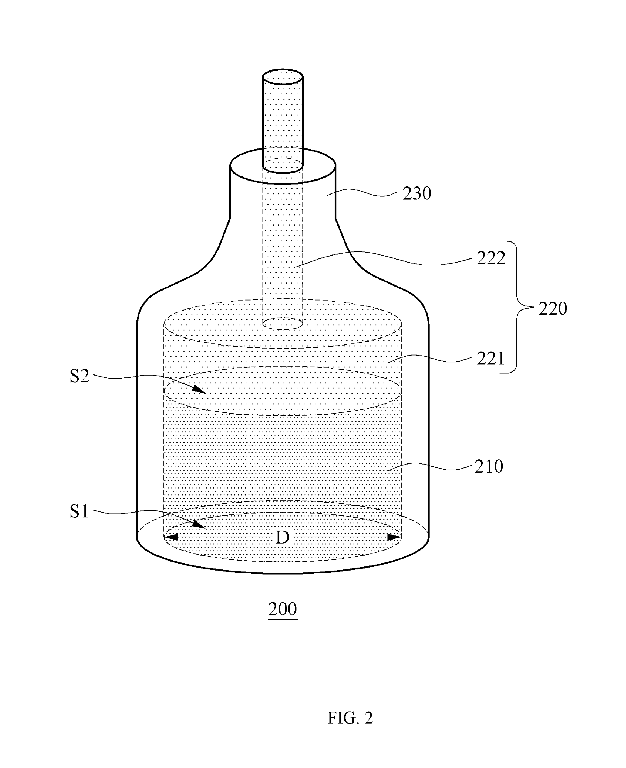
[0025]Hereinafter, a magnet terminal will be described in conjunction with FIGS. 2 and 3.

[0026]FIG. 2 illustrates a perspective of a magnet terminal and FIG. 3 illustrates a vertical section of the magnet terminal shown in FIG. 3.

[0027]As shown in FIGS. 2 and 3, a magnet terminal 200 may include a magnet laye...


PUM


Abstract

Disclosed is a magnet terminal and a jumper wire including the magnet terminal. The magnet terminal comprises a magnet layer, a metallic structure placed on the magnet layer and configured to conduct an electric signal with the magnet layer, and a tube configure to partly cover an outer surface of the metallic structure, then providing a low-cost solderless magnet terminal which is available for a component or electric/electronic circuit attachable to a magnet.

Description

CROSS-REFERENCE TO RELATED APPLICATIONS[0001]A claim for priority under 35 U.S.C. §119 is made to Korean Patent Application No. 10-2015-0071727 filed May 22, 2015, in the Korean Intellectual Property Office, the entire contents of which are hereby incorporated by reference.BACKGROUND[0002]1. Statement of Technical Field[0003]The present disclosure relates to terminals die conduction line connection of electric and electronic experimental circuit boards. More particularly, the present disclosure relates to solderless magnet terminals capable of facilitating electrical connection with electric / electronic circuits or components which are attachable to magnets.[0004]2. Description of Related Art[0005]With rapid growth of Internet of Things (IoT) in recent years, open hardware is sprightly used in manufacturing hardware structures. There is arising a need of preparing apparatuses or tools intuitively and easily available for forming circuits even by a beginner who starts electric / electro...

Claims


Application Information

Patent Timeline
IPC IPC(8): H01R11/30
CPCH01R11/30H01R4/72
Inventor KIM, SUGHUI
Owner KOREA UNIV RES & BUSINESS FOUND
Why Eureka
Try Eureka