
Electronic device with antenna device

Active Publication Date: 2016-11-24
SAMSUNG ELECTRONICS CO LTD
View PDF1 Cites 53 Cited by
  • Summary
  • Abstract
  • Description
  • Claims
  • Application Information

AI Technical Summary

Benefits of technology

The patent text describes a technology where an electronic device can use a metallic material in a part of its case to enhance its appearance and function as an antenna. By splitting the metal part of the case and using each section as a separate conductor, the device can work in different frequency bands. This allows for better wireless communication and ensures that signals do not interfere with each other. The device is also designed to be mechanically rigid, with power feeding and ground-connection points spaced apart. Overall, this technology improves the appearance and functionality of electronic devices.

Problems solved by technology

However, in a miniaturized electronic device, such as a mobile communication terminal, it may be difficult to secure a space for arranging an antenna device.
Furthermore, although it is necessary to arrange a plurality of antenna devices (or radiating conductors) in order to enable an electronic device to operate in a plurality of different frequency bands, it may be difficult to secure a space for installing such antenna devices in a miniaturized electronic device.
In addition, in an electronic device in which a metallic material is used as a case member in order to make the external appearance aesthetically desirable and to ensure shock resistance and the like, it may be difficult to secure the performance of an antenna device.

Method used


Image

  • Electronic device with antenna device
  • Electronic device with antenna device
  • Electronic device with antenna device

Examples


Embodiment Construction

[0035]Hereinafter, various embodiments of the present disclosure will be described with reference to the accompanying drawings. However, it should be understood that the present disclosure is not limited to the particular forms disclosed herein, rather, the present disclosure should be construed to cover various modifications, equivalents, and / or alternatives of embodiments of the present disclosure. In describing the drawings, similar reference numerals may be used to designate similar constituent elements.

[0036]In an embodiment of the present disclosure, the expressions “A or B”, “at least one of A or / and B”, or “one or more of A or / and B” may include all possible combinations of the items listed. For example, the expressions “A or B”, “at least one of A and B”, or “at least one of A or B” refer to all of (1) including at least one A, (2) including at least one B, or (3) including all of at least one A and at least one B.

[0037]The expressions “a first”, “a second”, “the first”, or...


PUM


Abstract

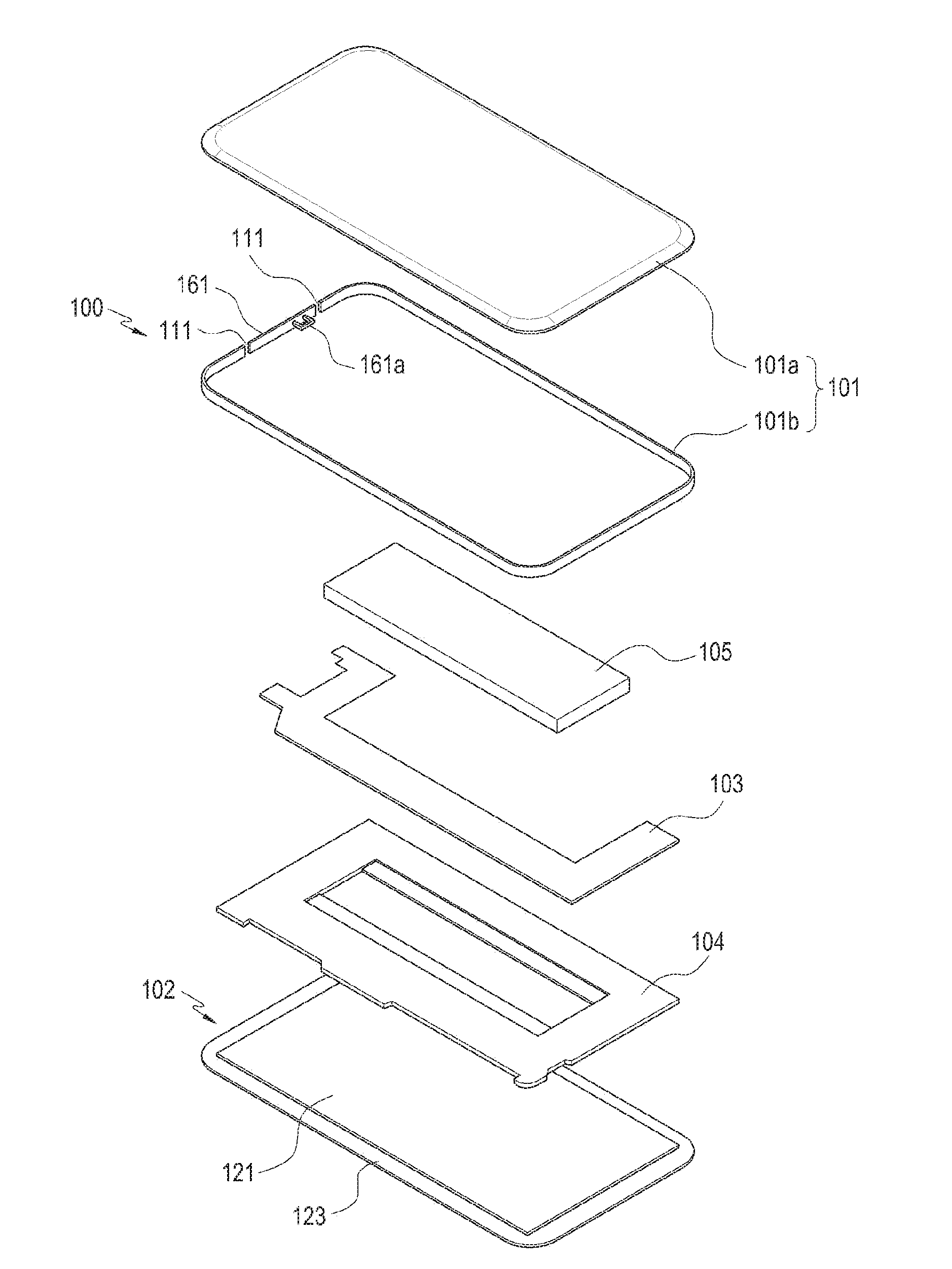
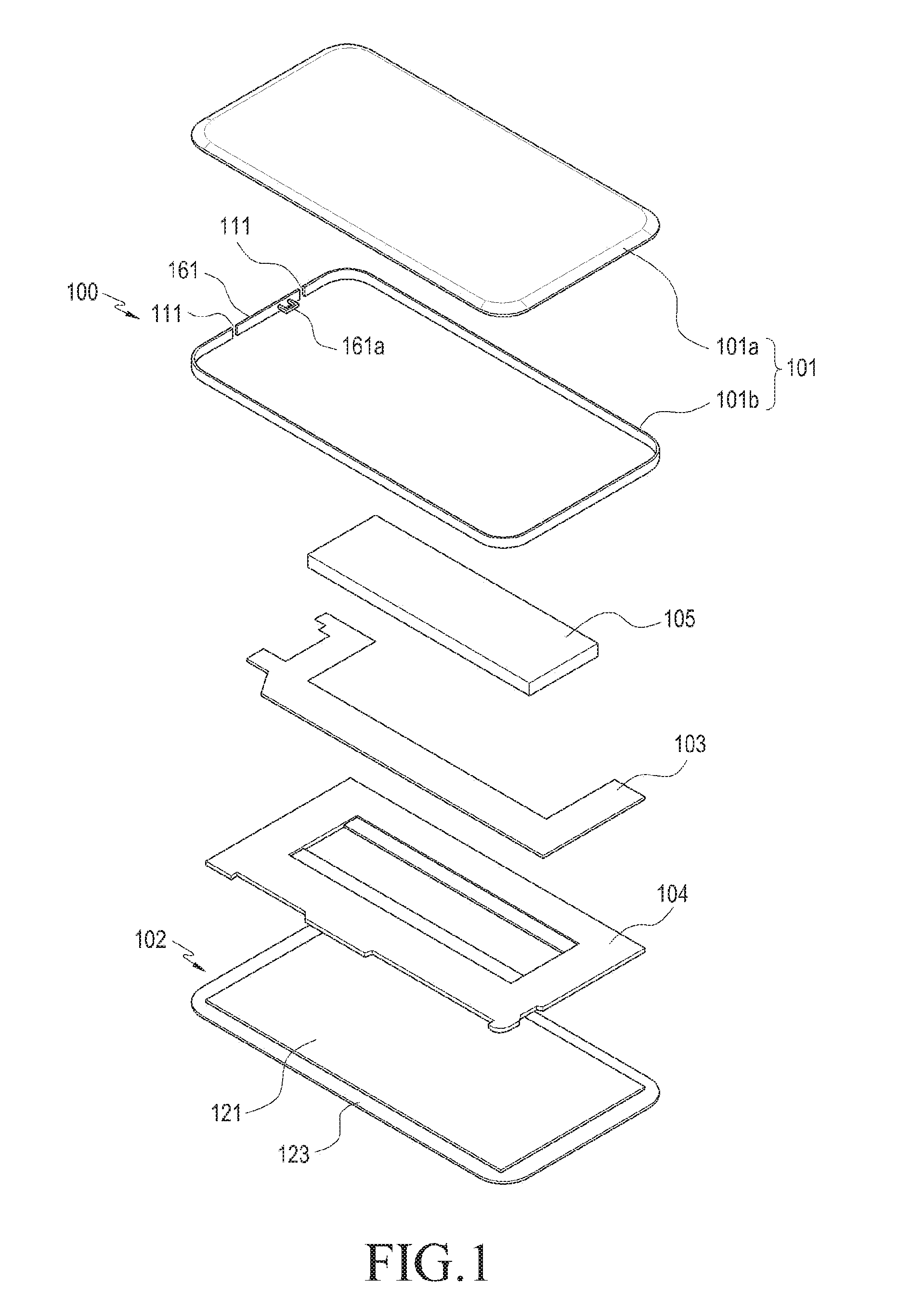
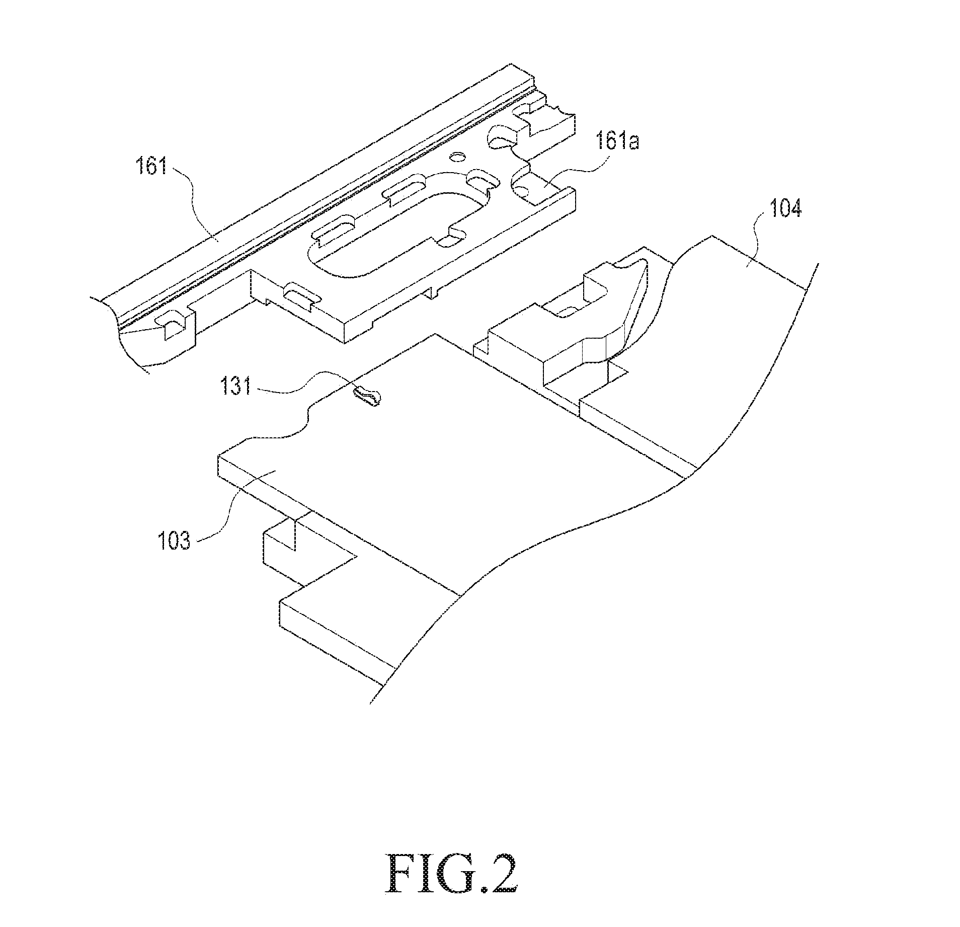
An electronic device with an antenna device is provided. The electronic device includes a case member that includes a first face, a second face disposed opposite to the first face, and side walls that enclose a space between the first face and the second face, a first metallic member that forms at least a portion of the side walls of the case member or is formed adjacent to the side walls, a metal pattern disposed within the case member and extends from a portion of the first metallic member to another portion of the first metallic member, the first metallic member and the metal pattern electrically forming at least a portion of a closed loop, a wireless communication circuit electrically connected to a portion of the metal pattern, a ground member positioned within the case member, and a portion of the metal pattern disposed adjacent to the ground member.

Description

PRIORITY[0001]This application claims priority under 35 U.S.C. §119(a) to Korean Patent Application Serial No. 10-2015-0069476, which was filed in the Korean Intellectual Property Office on May 19, 2015, the entire content of which is incorporated herein by reference.BACKGROUND[0002]1. Field of the Disclosure[0003]The present disclosure generally relates to an electronic device and more particularly to an electronic device that is capable of transmitting / receiving a radio frequency (RF) signal.[0004]2. Description of the Related Art[0005]Typically, an electronic device refers to a device that performs a specific function according to a stored program (e.g., an electronic scheduler, a portable multimedia reproducer, a mobile communication terminal, a tablet PC, an image / sound device, a desktop / laptop PC, a vehicular navigation system, or a home appliance). For example, such an electronic device may output information stored therein as sound or an image. As the degree of integration o...

Claims


Application Information

Patent Timeline
IPC IPC(8): H04B1/3888H01Q9/04H01Q1/24H01Q7/00G06F1/16H05K5/02
CPCH04B1/3888G06F1/1656H05K5/0247H01Q9/0407H01Q7/00H01Q9/0421H01Q1/243H01Q1/44H01Q1/50H01Q21/00H04M1/026H01Q1/48H01Q9/42H01Q21/28
Inventor SEOL, KYUNG-MOONKIM, JI-HOCHOE, JAE-WONPARK, GYU-BOKLEE, JAE-MOON
Owner SAMSUNG ELECTRONICS CO LTD
Learn More