Image analysis apparatus and image analysis method

an image analysis and image technology, applied in the field of image analysis apparatus and image analysis method, can solve the problems that the on-vehicle camera may change without the driver's knowledge, and achieve the effect of high accuracy

Active Publication Date: 2016-12-01
DENSO CORP
View PDF5 Cites 13 Cited by
  • Summary
  • Abstract
  • Description
  • Claims
  • Application Information

AI Technical Summary

Problems solved by technology

The mounting position or angle (hereinafter simply referred to as a mounting position) of an on-vehicle camera may, however, change without a driver's knowledge due to vibration or external force while the vehicle is under travel or stop.

Method used


Image

  • Image analysis apparatus and image analysis method
  • Image analysis apparatus and image analysis method
  • Image analysis apparatus and image analysis method

Examples


first embodiment

A. Apparatus Configuration

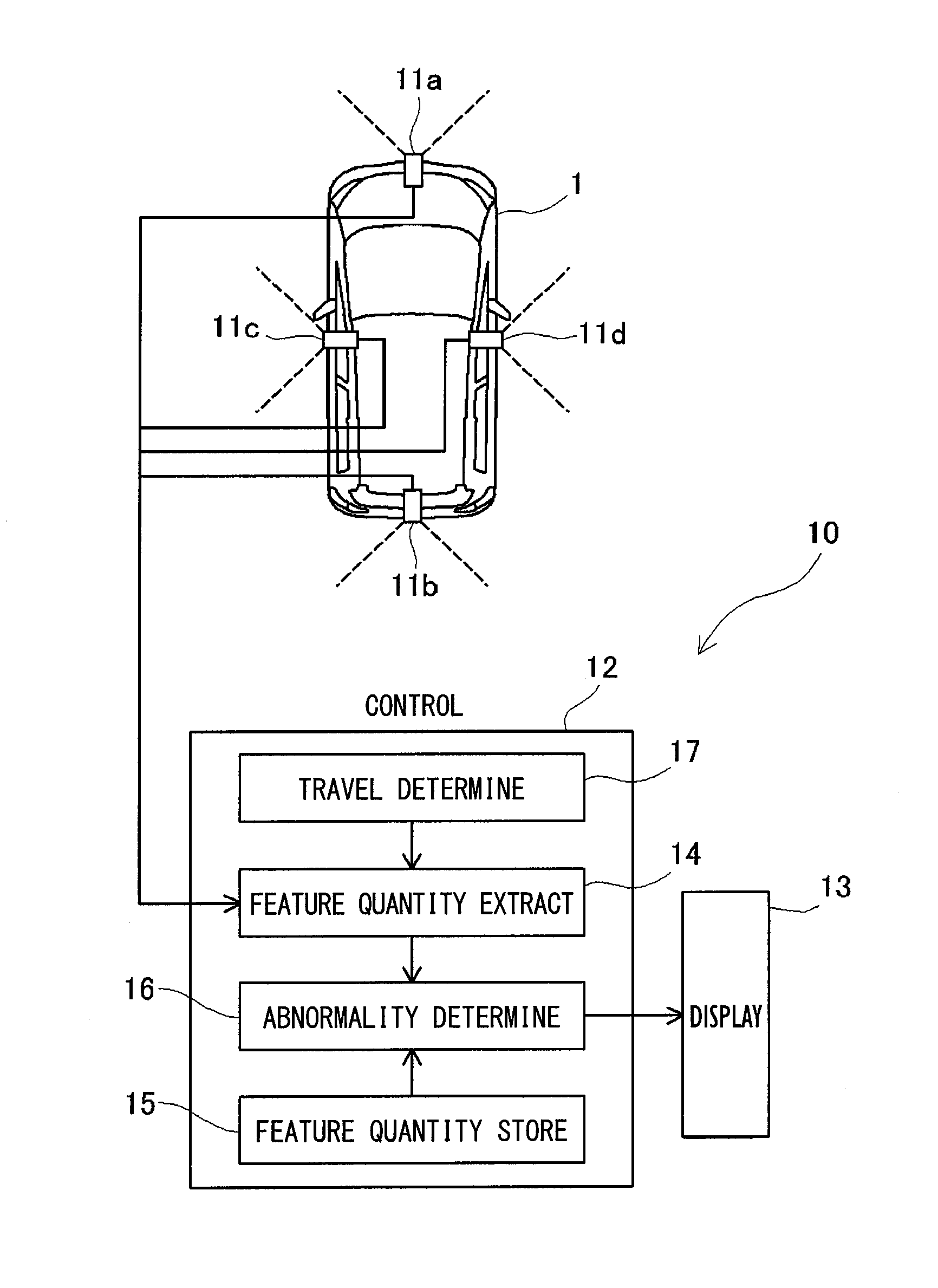
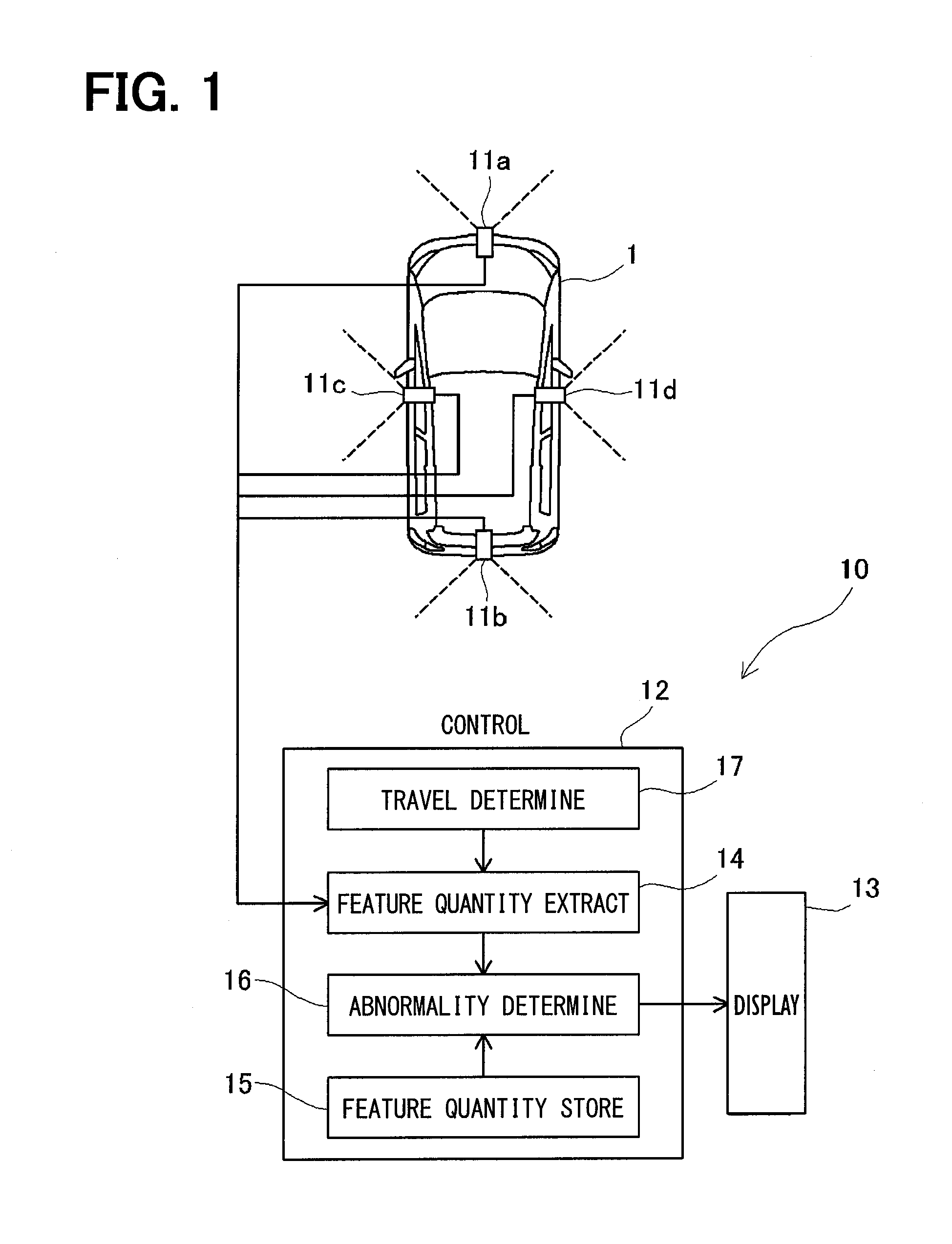
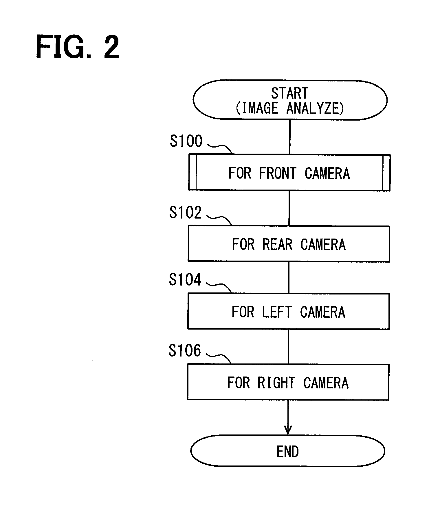
[0025]FIG. 1 illustrates a configuration of the image analysis apparatus 10 disposed in a vehicle 1 (referred to also as a host vehicle). The image analysis apparatus 10 according to a first embodiment analyzes images captured by on-vehicle cameras 11a-11d (front camera 11a, rear camera 11b, left camera 11c, and right camera 11d), which are mounted on the front, rear, left, and right of the vehicle 1, determines whether the on-vehicle cameras 11a-11d are mounted in respective abnormal positions, and notifies the results of determination. Although details are not given here, the on-vehicle cameras 11a-11d monitor the area around the vehicle 1, and a system separate from the image analysis apparatus 10 detects lane positions, obstacles, and pedestrians based on images captured by the on-vehicle cameras 11a-11d. Therefore, the on-vehicle cameras 11a-11d are mounted in predetermined positions of the vehicle 1 and at predetermined angles (the purpose of adjustin...

first modification

C-1. First Modification

[0052]The first embodiment calculates the brightness value of each pixel in the entire region of the front camera image (S204 of FIG. 3) and compares the “currently captured front camera image” against the “previously captured front camera image” on an individual pixel basis (S206). Meanwhile, a first modification calculates the brightness value of a pixel in a region (particular region) where the brightness value is likely to change when the front camera 11a is mounted in a normal position, and then compares the “currently captured front camera image” against the “previously captured front camera image”. That is, the first modification does not perform a process of calculating the brightness value or a process of comparing the “currently captured front camera image” against the “previously captured front camera image” on a region that is unlikely to change even when the front camera 11a is mounted in a normal position.

[0053]A hatched portion in FIG. 8A repres...

second modification

C-2. Second Modification

[0056]The first embodiment compares the actual feature quantity (the amount of change in the brightness value of the currently captured front camera image and the amount of change in the brightness value of the front camera image during the monitoring period) against the ideal feature quantity (threshold ratio α, threshold count β, first predetermined amount, and second predetermined amount), which is obtained when the front camera 11a is mounted normally, on the assumption that the ideal feature quantity remains unchanged irrespective of the speed of the vehicle 1. Meanwhile, a second modification determines the ideal feature quantity based on the speed of the vehicle 1 and compares the ideal feature quantity against the actual feature quantity.

[0057]As the conditions around the vehicle 1 greatly vary with an increase in the speed of the vehicle 1 no matter whether the mounting position of the front camera 11a remains unchanged, the amount of change in the b...


PUM


Abstract

An image analysis apparatus is applied to an on-vehicle camera that captures an image of a predetermined monitoring region oriented in a predetermined direction referenced to a vehicle, to analyze an image captured by the on-vehicle camera. The image analysis apparatus includes (i) a storage section that stores a feature quantity of a monitoring region image obtained when an image of the monitoring region is captured by the on-vehicle camera, (ii) an extraction section that acquires an image captured by the on-vehicle camera and extracts a feature quantity of the image captured by the on-vehicle camera, and (iii) a notification section that compares the feature quantity of the image captured by the on-vehicle camera against the feature quantity of the monitoring region image to perform determination whether the on-vehicle camera is mounted in an abnormal position, and notifies a result of the determination.

Description

CROSS REFERENCE TO RELATED APPLICATION[0001]The present disclosure is based on Japanese Patent Application No. 2014-21572 filed on Feb. 6, 2014, the disclosure of which is incorporated herein by reference.TECHNICAL FIELD[0002]The present disclosure relates to an image analysis apparatus and an image analysis method, which detect whether the mounting position or angle of an on-vehicle camera mounted in a vehicle is abnormal.BACKGROUND ART[0003]Some recently available vehicles are capable of monitoring the area around a vehicle by using an on-vehicle camera. There is known a technology that captures the image of a forward view from the vehicle by using an on-vehicle camera mounted on the front of the vehicle, determines the position of a lane by analyzing the captured image, and detects obstacles and pedestrians. Further, there is a widespread technology that uses an on-vehicle camera mounted on the rear of a vehicle to display the image of a rearward view from the vehicle on a monito...

Claims


Application Information

Patent Timeline
Patent Type & Authority Applications(United States)
IPC IPC(8): B60R1/00
CPCB60R1/00G06K9/00805B60R2300/402G06V20/58
Inventor SHIGEMURA, SHUSAKU
Owner DENSO CORP
Why Eureka
Try Eureka