Supercharge Your Innovation With Domain-Expert AI Agents!

Prime mover arrangement and method for controlling speed and torque output of a prime mover arrangement

Active Publication Date: 2016-12-01
VOLVO LASTVAGNAR AB
View PDF9 Cites 1 Cited by
  • Summary
  • Abstract
  • Description
  • Claims
  • Application Information

AI Technical Summary

Benefits of technology

The patent text is discussing the issue of changing the speed and torque supplied from a prime mover to a transmission. This can result in less optimal fuel consumption for the load demanded, and it is desirable to find a way to avoid this. The technical effect of this patent is to provide a solution that reduces the complexity of changing engine speed and torque to the driveline without the need to change engine crankshaft speeds.

Problems solved by technology

However, changing the speed or torque demanded at the flywheel may result in it being necessary to operate the engine conditions that are less than optimal in terms of fuel consumption.
This makes it difficult to standardize drivetrain design.

Method used


Image

  • Prime mover arrangement and method for controlling speed and torque output of a prime mover arrangement
  • Prime mover arrangement and method for controlling speed and torque output of a prime mover arrangement
  • Prime mover arrangement and method for controlling speed and torque output of a prime mover arrangement

Examples


Embodiment Construction

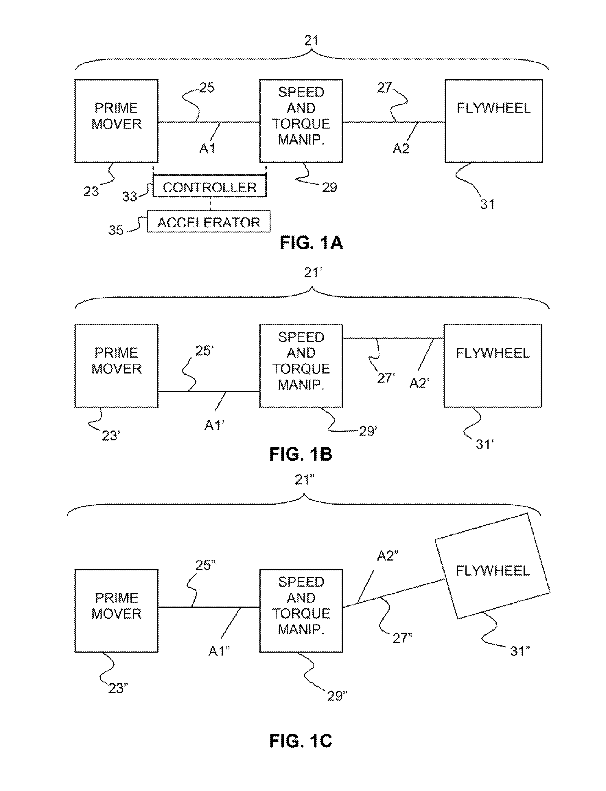
[0019]FIGS. 1A-1C show prime mover arrangements 21, 21′, and 2″ according to aspects of the present invention. Referring, for purposes of discussion, to the prime mover arrangement 21 shown in FIG. 1A, the prime mover arrangement comprises a prime mover 23 including a first shaft 25 driven by the prime mover, a second shaft 27, and a speed and torque manipulator 29 connected to the first shaft and to the second shaft. The speed and torque manipulator 29 permits manipulation of at least one ratio that is not 1:1 (“non-one-to-one”) or between a plurality, i.e., at least two, more preferably at least three, and still more preferably, an infinite number of different input / output ratios of speeds and torques input by the first shaft 25 and output to the second shaft 27. In a vehicle application, the prime mover arrangement 21 is typically connected upstream of other components of a drive train such as a flywheel 31 and a transmission (not shown), or a power take-off for a loading arm or ...


PUM


Abstract

A prime mover arrangement includes a prime mover (23) including a first shaft (25) driven by the prime mover, a second shaft (27), and a speed and torque manipulator (29) connected to the first shaft (25) and to the second shaft (27), the speed and torque manipulator permitting manipulation between at least one non-one-to-one ratio or a plurality of different input / output ratios of speeds and torques input by the first shaft and output to the second shaft. A method is also disclosed.

Description

BACKGROUND AND SUMMARY[0001]The present invention relates generally to prime movers and, more particularly, to prime movers of the type that are called upon to provide different levels of power and must deliver power at different shaft speeds and torques.[0002]When supplying power from a prime mover such as an internal combustion engine to, e.g., a transmission, it is often necessary to change the speed or torque supplied to a flywheel. The engine may initially be operated at a particular speed and torque combination that results in, e.g., optimal fuel consumption levels for the load demanded. However, changing the speed or torque demanded at the flywheel may result in it being necessary to operate the engine conditions that are less than optimal in terms of fuel consumption. It is desirable to reduce the complexity of changing engine speed and torque to the driveline in some manner that avoids the need to change engine crankshaft speeds to the ranges used by clutches, transmissions...

Claims


Application Information

Patent Timeline
IPC IPC(8): B60W30/188B60W10/101B60K17/08B60W10/08
CPCB60W30/188B60W10/08B60Y2300/52B60K17/08B60W10/101B60K6/105B60W10/04B60W10/06B60W10/10B60W30/1882B60W20/10Y02T10/84Y02T10/62Y02T10/40
Inventor JERWICK, JOHNGORDON, BRIANWERNER, TODD
Owner VOLVO LASTVAGNAR AB
Features
  • R&D
  • Intellectual Property
  • Life Sciences
  • Materials
  • Tech Scout
  • Unparalleled Data Quality
  • Higher Quality Content
  • 60% Fewer Hallucinations
Learn More