Chip discharge device of machine tool

Active Publication Date: 2016-12-08
DMG MORI SEIKI CO LTD
View PDF1 Cites 3 Cited by
  • Summary
  • Abstract
  • Description
  • Claims
  • Application Information

AI Technical Summary

Benefits of technology

The present invention provides a chip discharge device for a machine tool that can quickly and easily perform the coolant and chip discharge process without increasing costs. This solves the problems of existing methods and apparatuses and improves efficiency.

Problems solved by technology

However, in this discharge process, when the water level of the coolant is close to the bottom wall, it becomes difficult to flow, so that there is a problem that the part of the coolant easily remains inside the tank.
As such conventional devices, when the configuration in which the bottom wall of the coolant tank is inclined, in comparison with the configuration in which the bottom wall is flat, there are problems that it takes time and effort to provide the inclined bottom wall and the cost increases.

Method used


Image

  • Chip discharge device of machine tool
  • Chip discharge device of machine tool
  • Chip discharge device of machine tool

Examples


embodiment 1

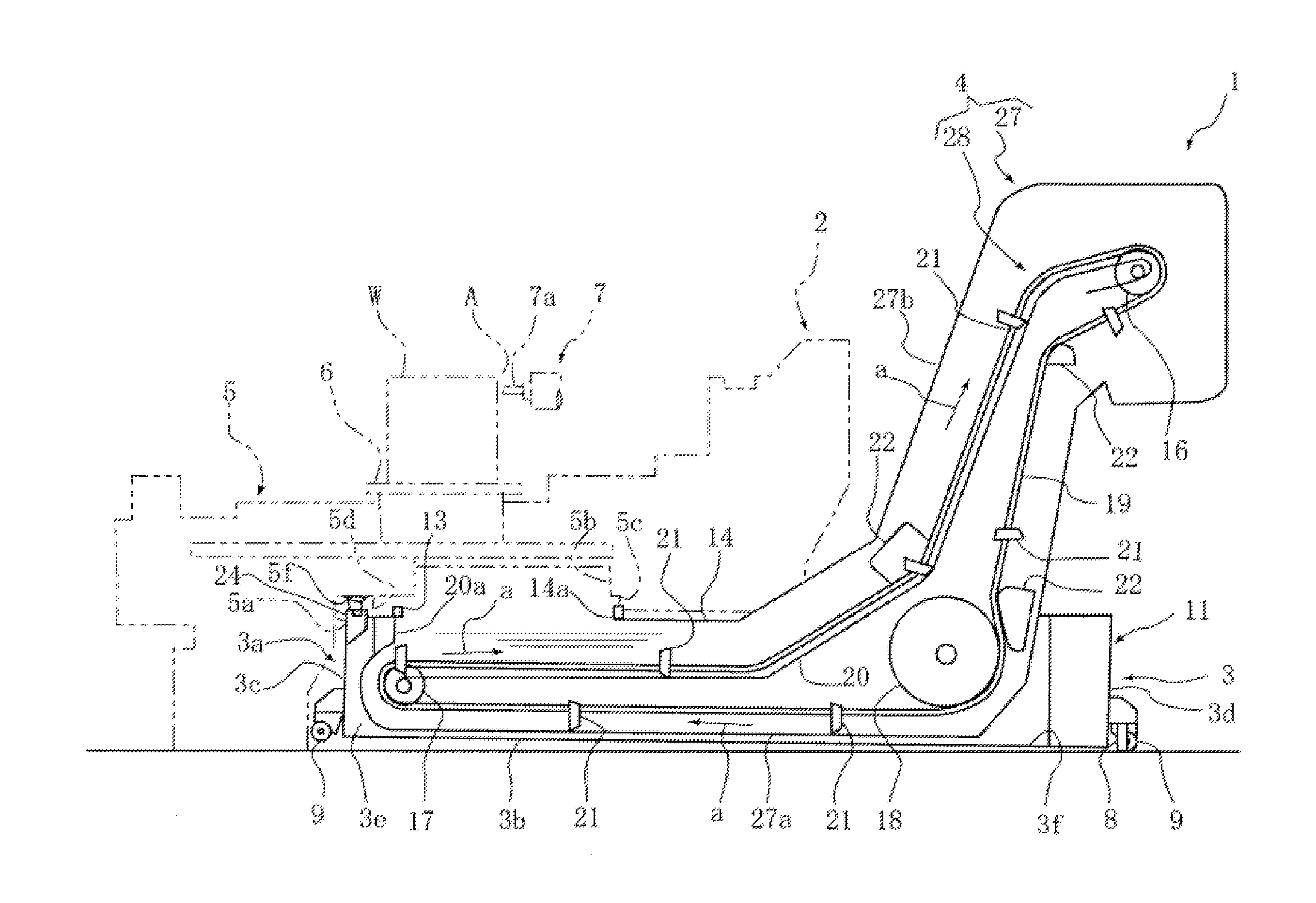
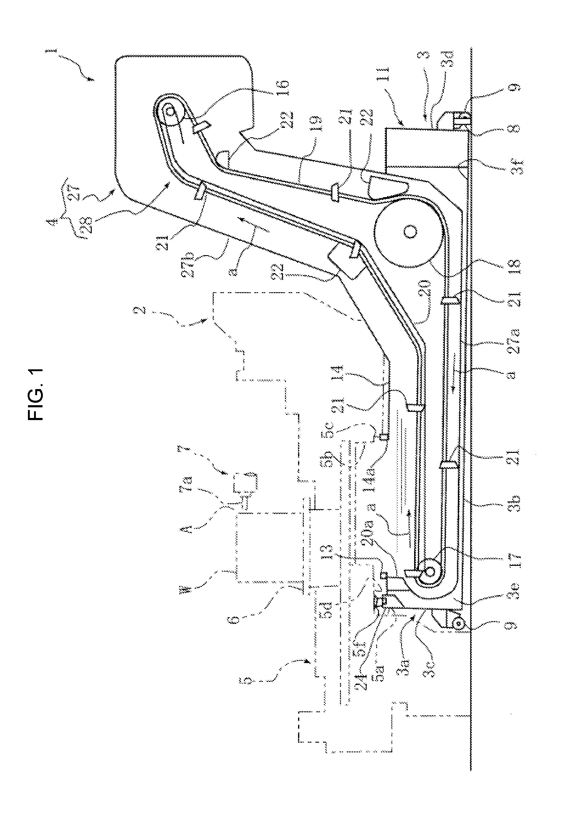
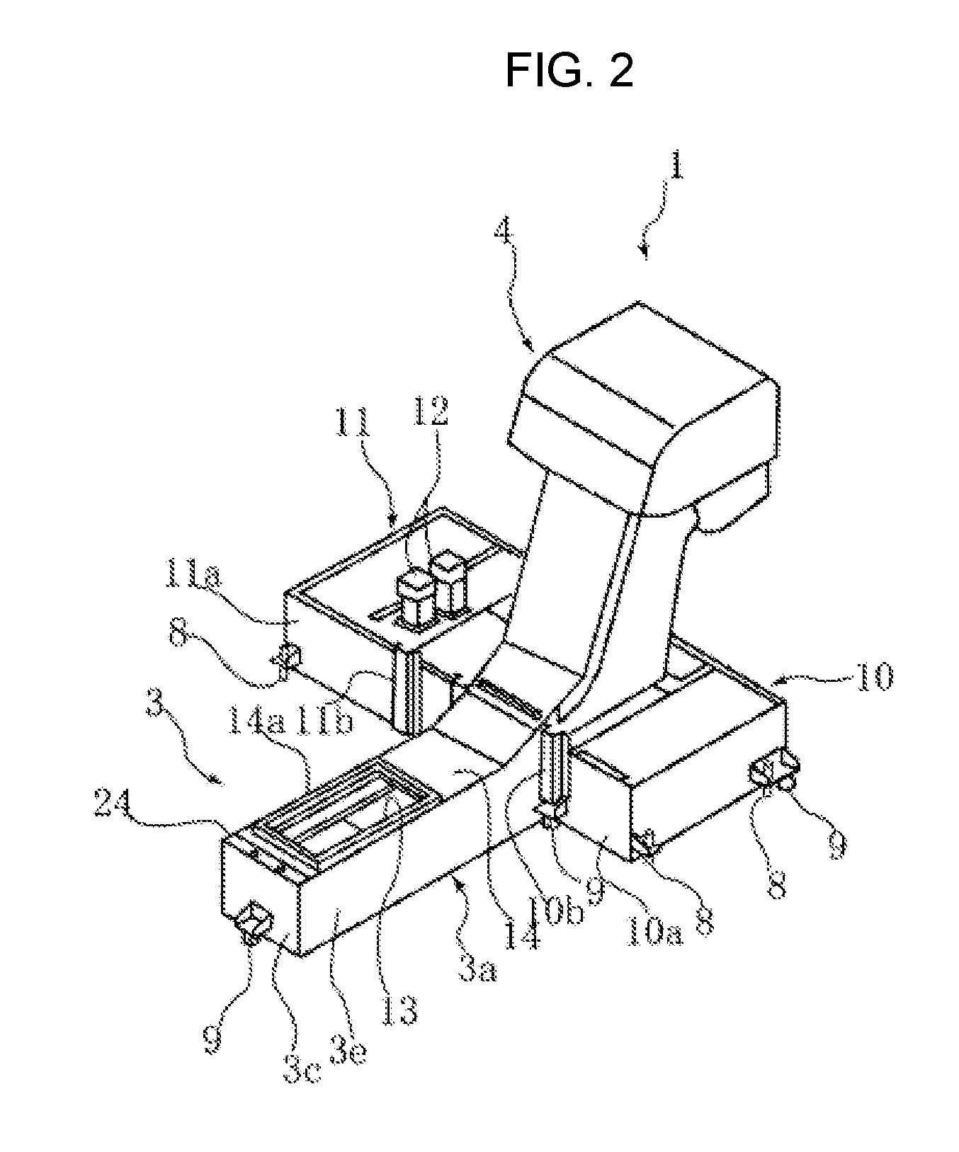
[0033]FIGS. 1 to 5 are the drawings to describe a chip discharge device of a machine tool according to embodiment 1 of the present invention. In the present embodiment, the indications “front (forward)”, “rear (rearward)”, “left” and “right” mean the front, rear, left and right of the machine when viewed from the machine front face.

[0034]In the drawings, reference numeral 1 denotes a chip discharge device provided in a machine tool such as a horizontal machining center 2, etc. The chip discharge device 1 is provided with a coolant tank 3, which stores coolant supplied to a machining point A of the horizontal machining center 2 and then dropped, and a chip conveyor 4 provided in a manner in which the lower part of the chip conveyor is stored inside the coolant tank 3 and discharging chips, which are generated at the machining point A and then dropped, to the outside of the machine.

[0035]The horizontal machining center 2 has a configuration in which a work W is mounted on a work table...


PUM

PropertyMeasurementUnit
Thicknessaaaaaaaaaa
Heightaaaaaaaaaa

Abstract

A chip discharge device of a machine tool includes a coolant tank storing coolant which is supplied to and dropped from a machining point, and a chip conveyor discharging chips which are generated at and dropped from the machining point, to an outside of the machine tool. A bottom wall of the coolant tank is inclined in a chip discharge side by mounting the coolant tank to the bed.

Description

CROSS-REFERENCE TO RELATED APPLICATIONS[0001]The present application claims priority under 35 U.S.C. 119 to Japanese Patent Application No. 2015-113662, filed on Jun. 4, 2015, the contents of which is incorporated herein by reference in its entirety.BACKGROUND OF THE INVENTION[0002]Field of the Invention[0003]The present invention relates to a chip discharge device of a machine tool provided with a coolant tank, which stores coolant, and a chip conveyor, which discharges chips to the outside of the machine.[0004]Description of the Related Art[0005]In this kind of chip discharge devices, most of the chips generated by machining a work are discharged to the outside of the machine, but there is a case where a part of the chips, specifically fine powdery chips, is accumulated in a bottom wall of a coolant tank. Therefore, it is necessary to regularly discharge the powdery chips inside the coolant tank, and also, it is necessary to discharge the coolant from the inside of the tank in ord...

Claims


Application Information

Patent Timeline
IPC IPC(8): B23Q11/00B01D21/24B01D21/00B23Q11/10
CPCB23Q11/0057B01D21/0012B01D21/2455B23Q11/1069B23Q11/0067B01D21/0015B01D2221/14
Inventor KAKUTANI, MASAHIDEOSHIMA, RYUTARO
Owner DMG MORI SEIKI CO LTD
Why Eureka
Try Eureka