
Eureka
For R&D, Eureka makes reading and utilizing patents & technical documents easy.
Eureka AIR
Designed for self-driven R&D workflows. Generate viable solutions, solve complex R&D challenges, empower your innovation with AI.

Eureka Materials
Designed for material experts only. Revolutionize your material R&D, from search, analyze, to developing new materials.

TechResearch
Generate reliable direction feasibility study reports for your R&D in just a few steps.

TechSeek
Discover and master advanced knowledge NOW. Basics, ideas, possibilities, all at once.

TechMind
As an expert in R&D Theories, TechMind can generates customized viable solutions instantly.

TechRisk
Analyze your overall solution with one click, know your potential R&D risks in advance.

TechMonitor
Get weekly tech updates, stay abreast of the latest tech innovations and key insights.
Method for controlling shape measuring apparatus
- Summary
- Abstract
- Description
- Claims
- Application Information
AI Technical Summary
Benefits of technology
Problems solved by technology
Method used
Image


Examples
first exemplary embodiment
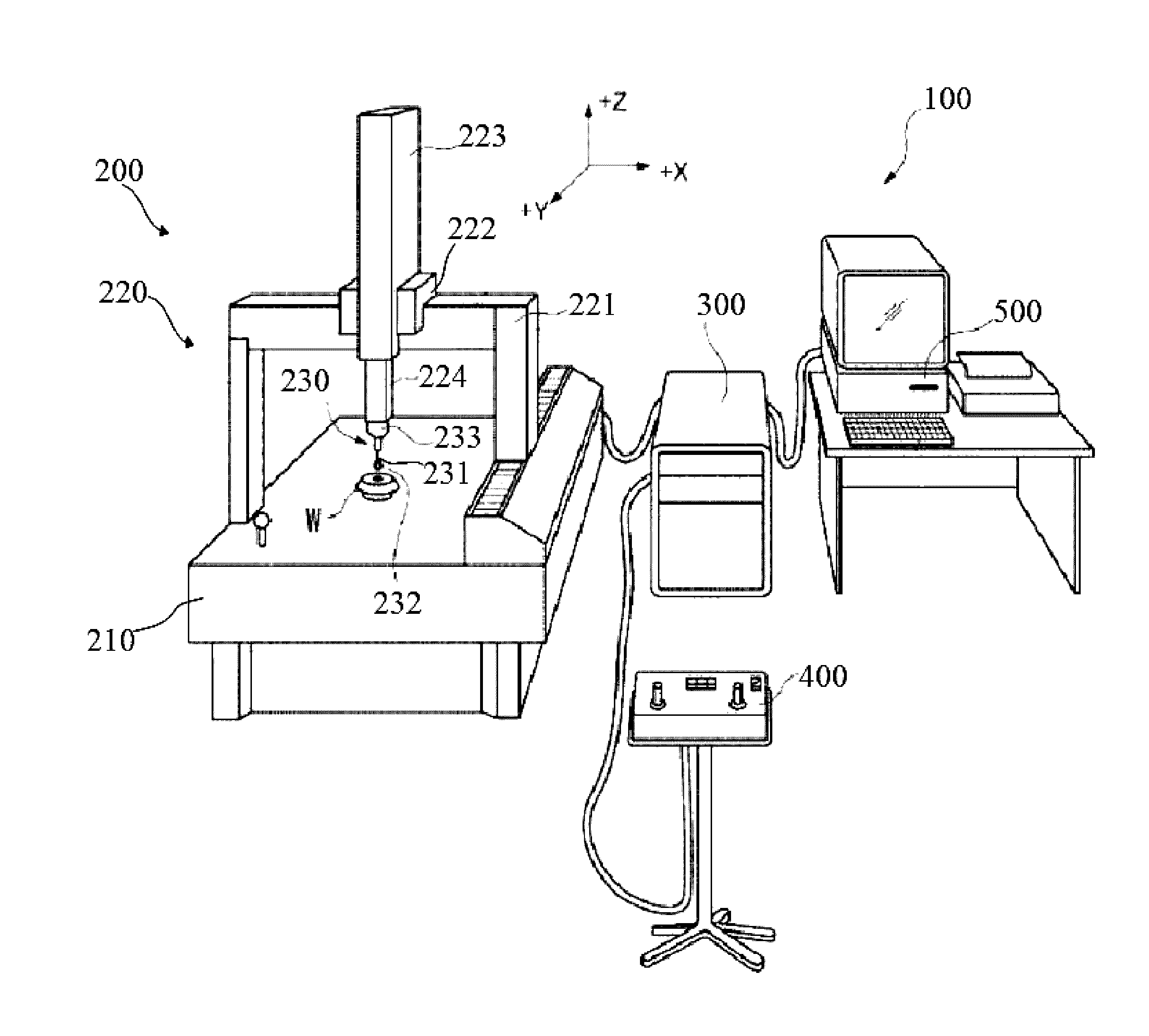
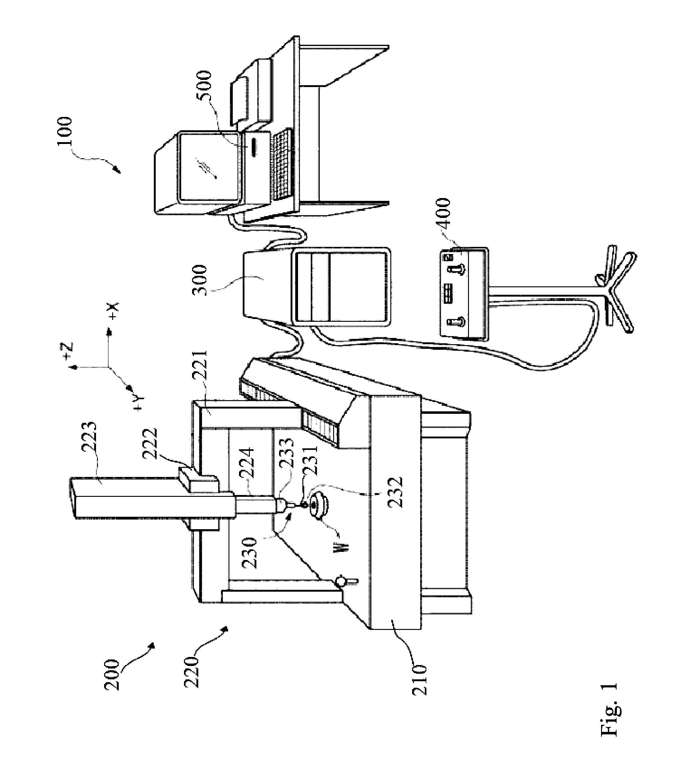
[0056]FIG. 1 is a diagram illustrating an entire configuration of a shape measuring system 100.
The basic configuration of the shape measuring system 100 has been known, but will be briefly described.
[0057]The shape measuring system 100 includes a coordinate measuring machine 200, a motion controller 300 which controls the drive of the coordinate measuring machine 200, and a host computer 500 which controls the motion controller 300 and executes necessary data processing.
[0058]The coordinate measuring machine 200 includes a base 210, a moving mechanism 220, and a probe 230.
[0059]The moving mechanism 220 includes a gate type Y slider 221, an X slider 222, a Z axis column 223, and a Z spindle 224. The Y slider 221 is provided slidably on the base 210 in a Y direction. The X slider 222 slides along a beam of the Y slider 221 in an X direction. The Z axis column 223 is secured to the X slider 222. The Z spindle 224 moves up and down inside the Z axis column 223 in a Z direction.
[0060]A d...
modified example 1
[0159]For reference, the case in which a “sine curve” is selected in a measurement path selection (ST250) will be described. FIG. 15 illustrates an example of a sine curve path for scanning measurement.
[0160]When a “sine curve” is selected as a measurement path, a screen to input information, such as a start point (θzy0, θz0), amplitude (θzH, θzL), the number of turns i, the number of sampling points N, is presented (FIG. 14).
[0161]Note that, θzH indicates the maximum value of θz, and θzL indicates the minimum value of θz.
[0162]With the information, measurement points (a point sequence) (r, φxy, θz) on a workpiece is indicated as follows:
φxy=φxy0+[360×{(k−1) / (N−1)}]
θz=(θzH+θzL) / 2±{(θzH−θzL) / 2}sin[360i×{(k−1) / (N−1)}]
[0163]If an object to be measured is a sphere, a spherical coordinates system is used, and if an object to be measured is a cylinder, a cylindrical coordinate system is used. Other processing is the same as above embodiment.
modified example 2
[0164]When the shape parameter is input (ST240), the center coordinates of the sphere have been input (FIG. 9). However, a menu of “automatic setting of center coordinates” may be added based on the assumption that accurate center coordinates in a machine coordinate system are not immediately obtained.
[0165]If it has been known that the shape is a sphere, the center coordinates can be calculated by measuring some points on a workpiece.
[0166]When the “automatic setting of center coordinates” is selected, the center coordinates may be obtained by, for example, preliminarily measuring some points on the workpiece by point measurement. The point measurement may be performed automatically or manually by a user.
[0167]Note that, the present invention is not limited to the above exemplary embodiments, and can be modified without departing from the scope of the invention.
[0168]In the above embodiments, active nominal scanning measurement has been mainly described, but the “active nominal sca...
PUM
 Abstract
Description
Claims
Application Information
 - R&D Engineer
- R&D Manager
- IP Professional
- Industry Leading Data Capabilities
- Powerful AI technology
- Patent DNA Extraction
Browse by: Latest US Patents, China's latest patents, Technical Efficacy Thesaurus, Application Domain, Technology Topic, Popular Technical Reports.
© 2024 PatSnap. All rights reserved.Legal|Privacy policy|Modern Slavery Act Transparency Statement|Sitemap|About US| Contact US: help@patsnap.com