Temperature compensation circuit and sensor device
a temperature compensation circuit and sensor technology, applied in the field of temperature compensation circuits and sensor devices, can solve the problems of limited range in which temperature compensation circuits can be used, and the inability to adjust the temperature compensation amount solely and independently, and achieve the effect of small circuit scal
- Summary
- Abstract
- Description
- Claims
- Application Information
AI Technical Summary
Benefits of technology
Problems solved by technology
Method used
Image

Examples
first embodiment
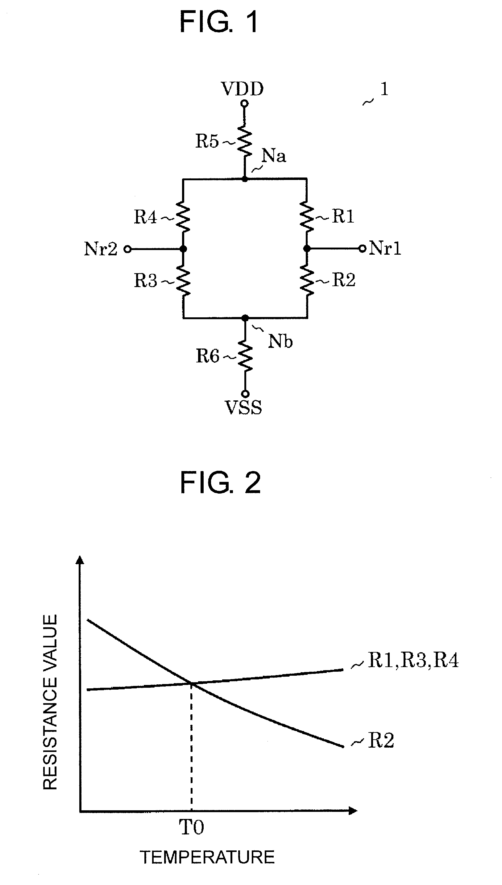
[0025]FIG. 1 is a circuit diagram of a temperature compensation circuit according to a first embodiment of the present invention. A temperature compensation circuit 1 according to the first embodiment includes resistors R1 to R6.
[0026]A first output terminal Nr1 is connected to a node between the resistor R1 and the resistor R2. A second output terminal Nr2 is connected to a node between the resistor R3 and the resistor R4. A first voltage terminal Na is formed at a node between the resistor R1 and the resistor R4, and a second voltage terminal Nb is formed at a node between the resistor R2 and the resistor R3. The resistor R5 is connected between a power supply terminal VDD and the first voltage terminal Na, and the resistor R6 is connected between a ground terminal VSS and the second voltage terminal Nb.
[0027]Voltages at the first output terminal Nr1, at the second output terminal Nr2, at the first voltage terminal Na, and at the second voltage terminal Nb are represented by Vr1, ...
second embodiment
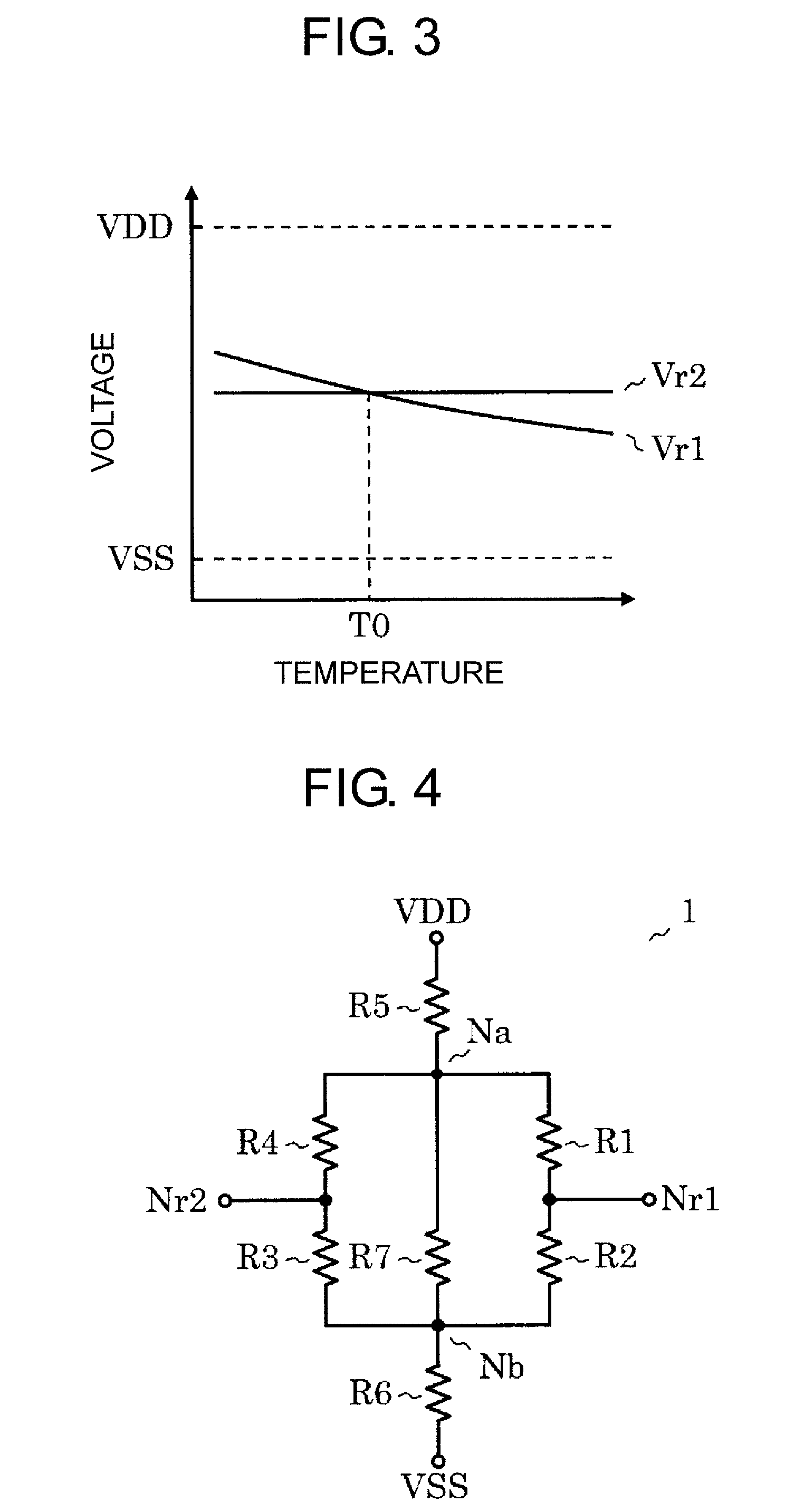
[0047]FIG. 4 is a circuit diagram of a temperature compensation circuit according to a second embodiment of the present invention. The second embodiment is different from the first embodiment illustrated in FIG. 1 in that a resistor R7 is added. The added resistor R7 is connected between the first voltage terminal Na and the second voltage terminal Nb. Through adding the resistor R7, a resistor Ra′ equivalent to the resistors R1 to R4 and the resistor R7 is expressed by the following expression.
Ra′=R7R7+Ra×Ra(19)
[0048]Here, Ra is the same as the resistor Ra equivalent to the resistors R1 to R4 expressed by Expression (11) in the first embodiment. Further, when a resistor equivalent to the resistors R1 to R7 is represented by Rt′, the equivalent resistor Rt is expressed by the following expression.
Rt′=R5+R6+Ra′ (20)
[0049]Similarly to the process of deriving Expression (17) from Expression (13) according to the first embodiment, (Va−Vb) is determined as in the following expressions.
[...
third embodiment
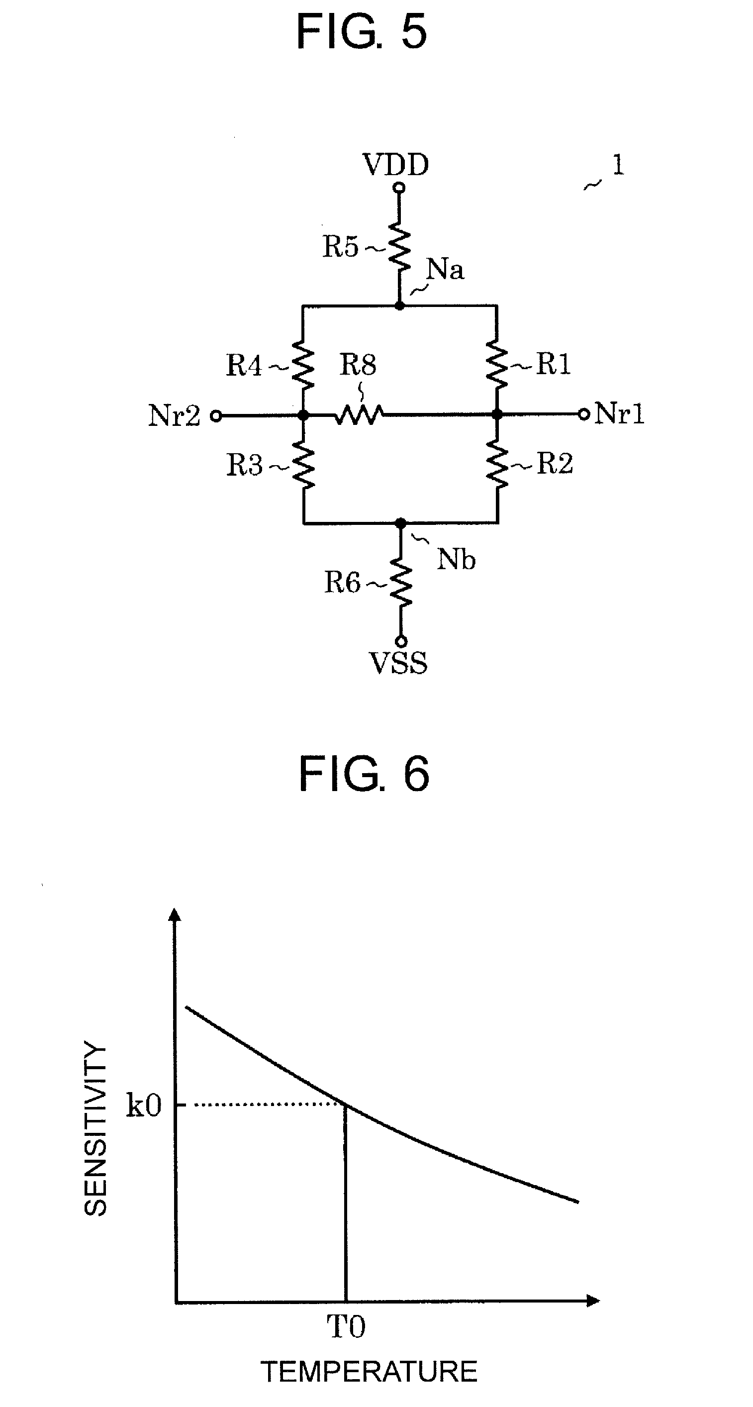
[0057]FIG. 5 is a circuit diagram of a temperature compensation circuit according to a third embodiment of the present invention. The third embodiment is different from the first embodiment illustrated in FIG. 1 in that a resistor R8 is added. The added resistor R8 is connected between the first output terminal Nr1 and the second output terminal Nr2. A voltage Vr1′ at the first output terminal Nr1, a voltage Vr2′ at the second output terminal Nr2, and a temperature compensation voltage ΔVr′ in this embodiment are calculated as follows. When currents flowing through the resistors R1 to R4 and R8 are represented by I1 to I14 and I8, respectively, the relationships of the respective currents are expressed by the following expressions.
I1=Va-Vr1′R1(26)I2=Vr1′-VbR2(27)I3=Vr2′-VbR3(28)I4=Va-Vr2′R4(29)I8=Vr2′-Vr1′R8(30)I4=I3+I8(31)I2=I1+I8(32)
[0058]From Expression (26) to Expression (32), the temperature compensation voltage ΔVr′=Vr1′−Vr2′ is calculated as follows.
ΔVr′-R2×R4-R1×R3(R1+R2)×(R...
PUM
 Abstract
Description
Claims
Application Information
 - R&D
- Intellectual Property
- Life Sciences
- Materials
- Tech Scout
- Unparalleled Data Quality
- Higher Quality Content
- 60% Fewer Hallucinations
Browse by: Latest US Patents, China's latest patents, Technical Efficacy Thesaurus, Application Domain, Technology Topic, Popular Technical Reports.
© 2025 PatSnap. All rights reserved.Legal|Privacy policy|Modern Slavery Act Transparency Statement|Sitemap|About US| Contact US: help@patsnap.com