

Overheat detection circuit and power supply apparatus
- Summary
- Abstract
- Description
- Claims
- Application Information
AI Technical Summary
Benefits of technology
Problems solved by technology
Method used
Image

Examples
Embodiment Construction
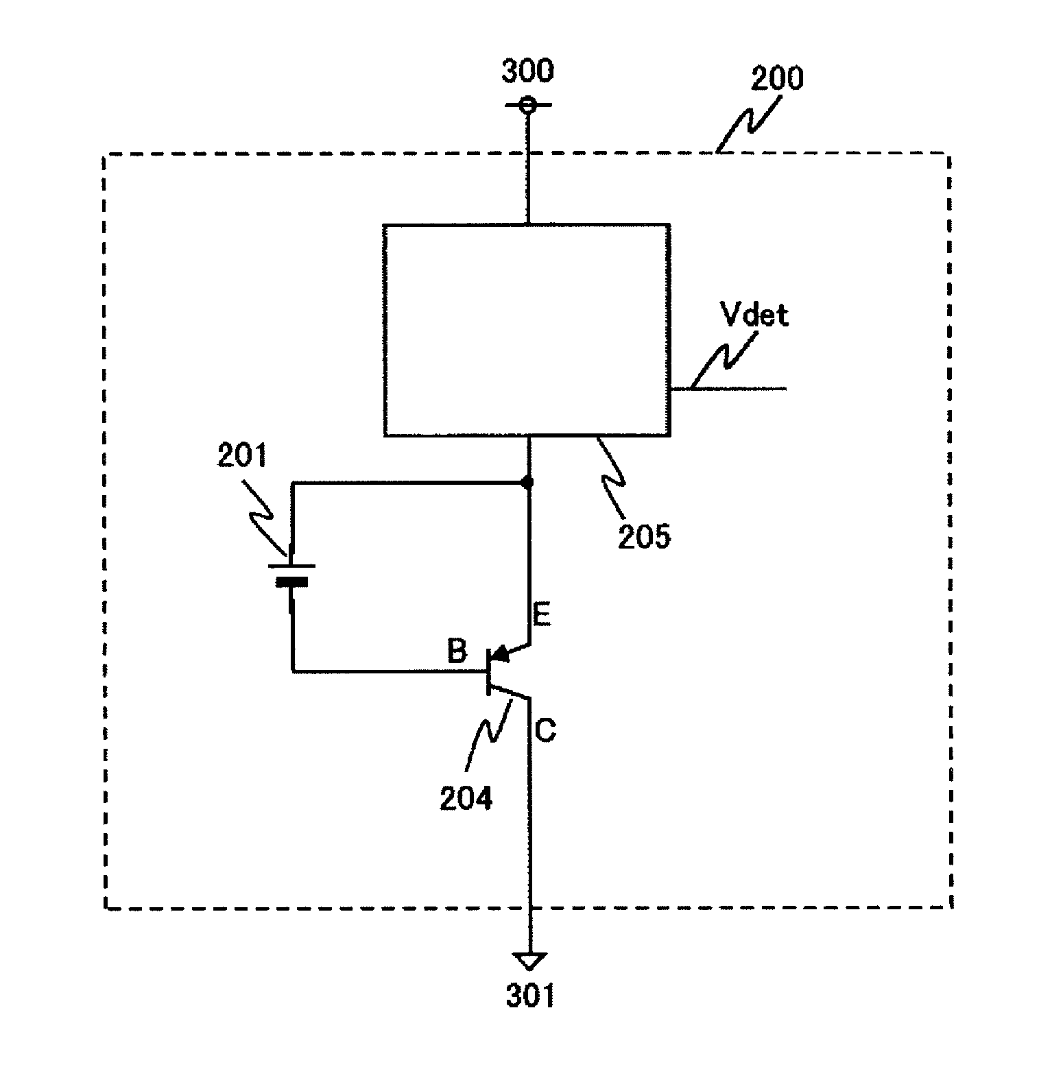
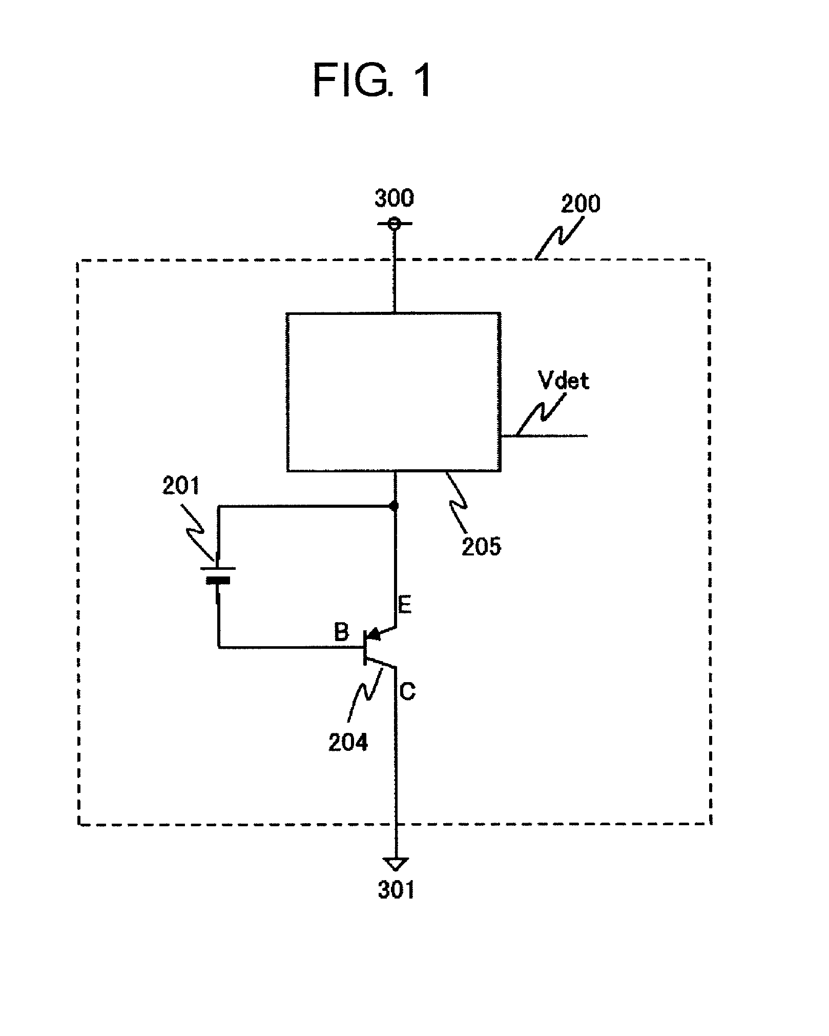
[0023]FIG. 1 is a block diagram for illustrating an overheat detection circuit according to an embodiment of the present invention.
[0024]The overheat detection circuit 200 according to this embodiment includes a reference voltage circuit 201, a parasitic bipolar transistor 204, and a current detection circuit 205. The overheat detection circuit according to this embodiment is realized by actively utilizing the parasitic bipolar transistor as a temperature sensing element in a CMOS process.
[0025]The reference voltage circuit 201 is connected between a base and an emitter of the parasitic bipolar transistor 204. The parasitic PNP bipolar transistor 204 has a collector electrically connected to a p-type substrate. This connection may be through a diffused resistor or a well resistor.
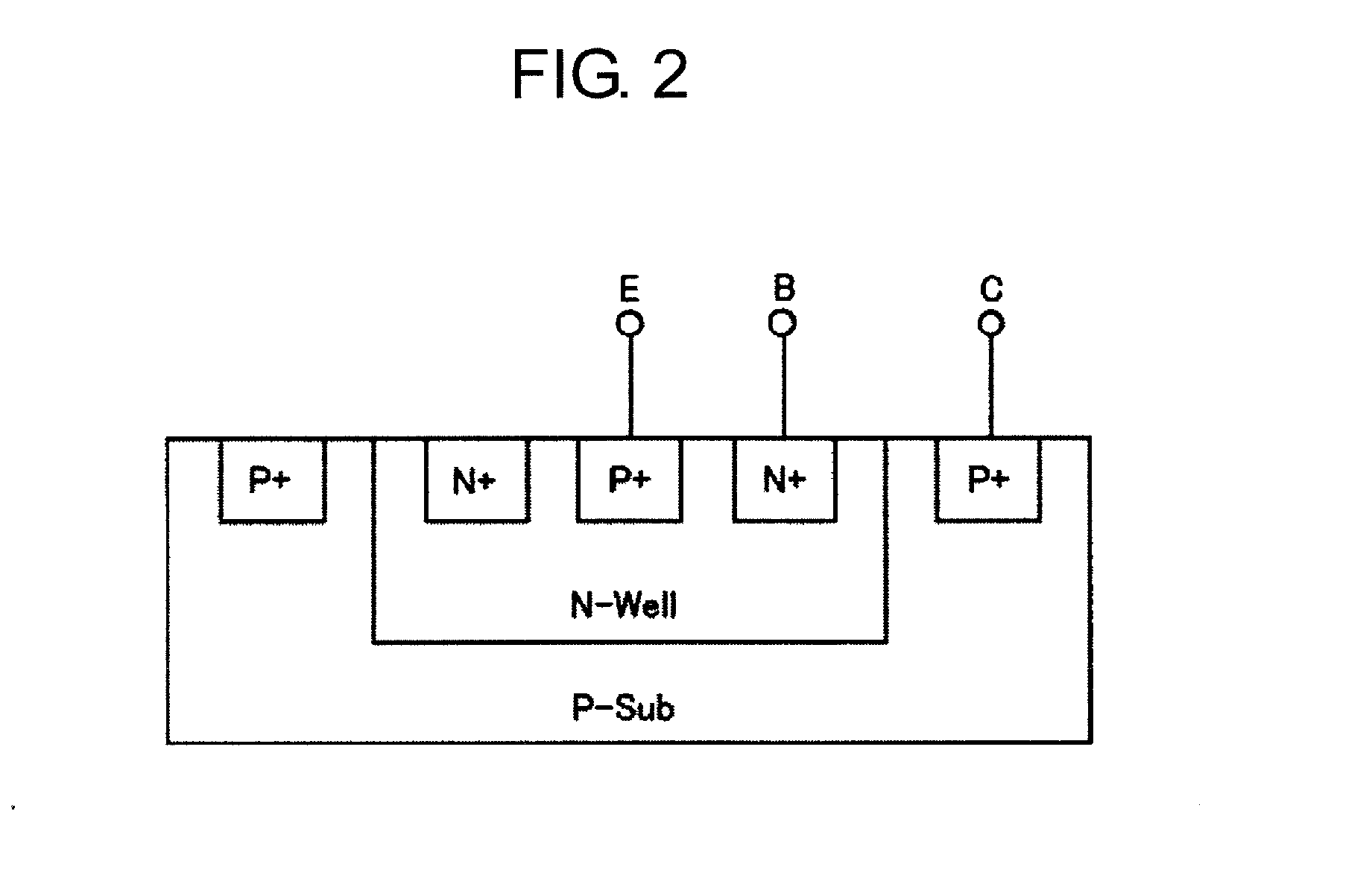
[0026]FIG. 2 is a view for illustrating an example of a cross-sectional structure of a parasitic bipolar transistor of the overheat detection circuit 200 according to this embodiment. The current detection ...
PUM
 Abstract
Description
Claims
Application Information