Wobble signal demodulation method and wobble signal demodulator

Inactive Publication Date: 2009-02-12
RENESAS ELECTRONICS CORP
View PDF2 Cites 0 Cited by
  • Summary
  • Abstract
  • Description
  • Claims
  • Application Information

AI Technical Summary

Benefits of technology

[0047]Note that the wobble signal demodulation method of the above embodiment replaced by a device or a system is effective as an embodiment of the present invention.
[0048]According to the technolog

Problems solved by technology

The synchronization signal is incorrectly detected mainly because of disturbance due to a spindle operation or a physical defect of a disc, and crosstalk.
As a result, there arises a problem in that the correct address information cannot be obtained and recording or reproduction operation may be carried out in the incorrect position on the disc.
As a result, recording or reproducing processing may be carried out in an incorrect position on a disc.
Especially when the amplitude of the wobble signal is small, the decoding may be incorrectly performed.
In a period in which the resynchronization is performed, it is impossible to decode address information and it is also impossible to perform recording or reproducing processing.
For this reason, the continual resynchronization deteriorates the processing efficiency of the system.

Method used


Image

  • Wobble signal demodulation method and wobble signal demodulator
  • Wobble signal demodulation method and wobble signal demodulator
  • Wobble signal demodulation method and wobble signal demodulator

Examples


Embodiment Construction

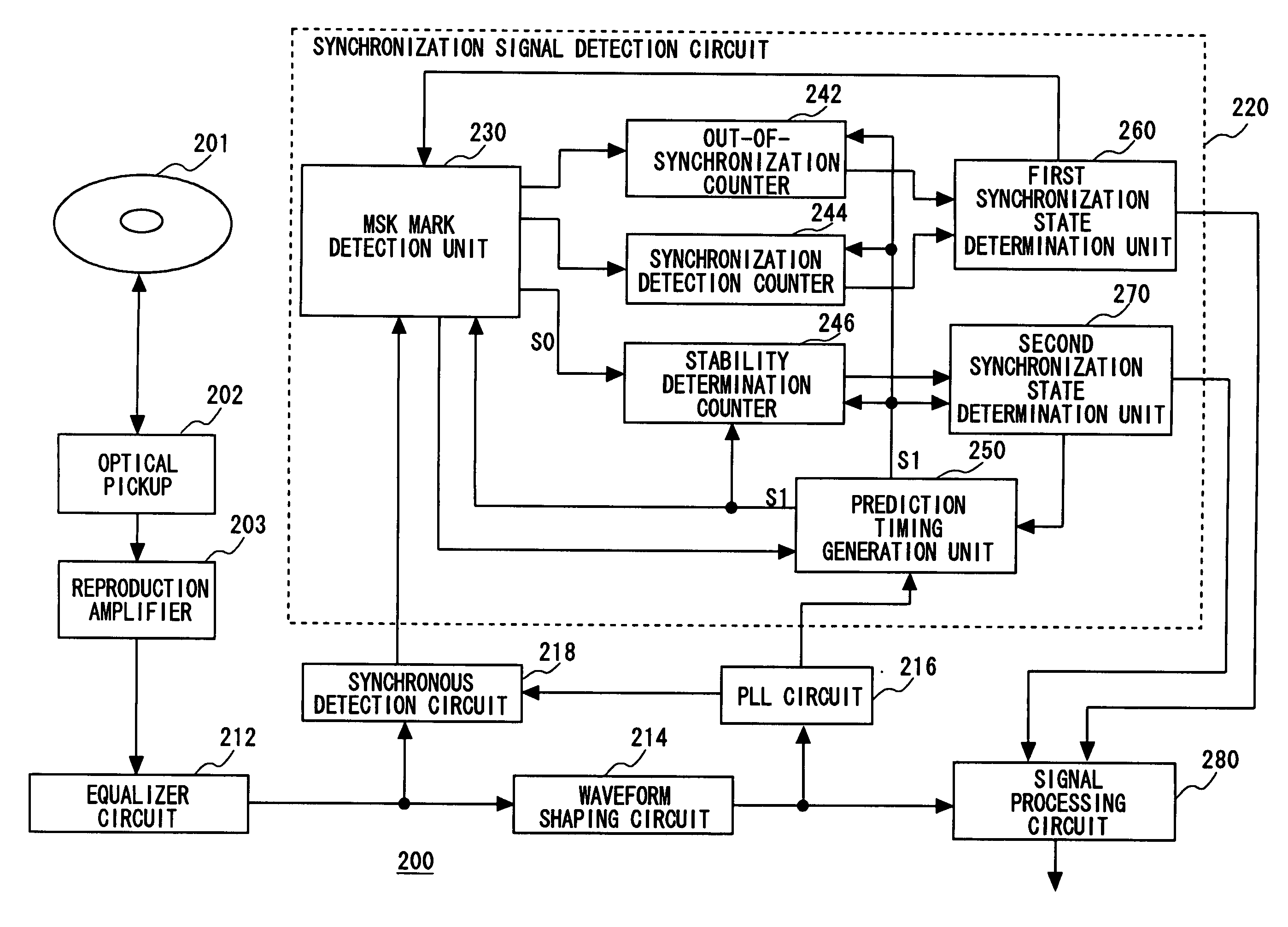
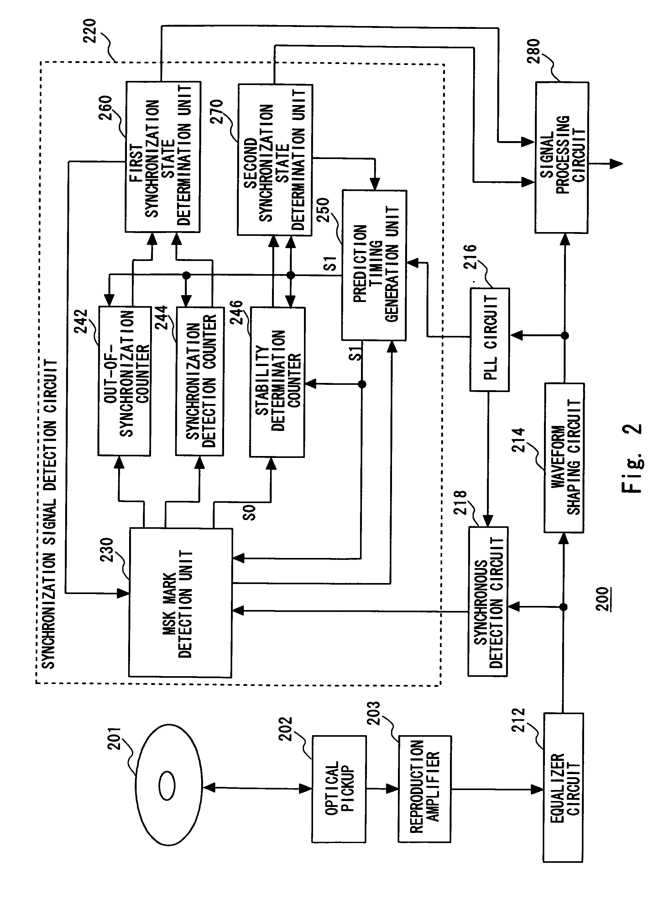
[0063]The invention will now be described herein with reference to illustrative embodiments. Those skilled in the art will recognize that many alternative embodiments can be accomplished using the teachings of the present invention and that the invention is not limited to the embodiments illustrated for explanatory purposes.

[0064]Prior to explanation of specific embodiments of the present invention, the principle of the present invention is first described.

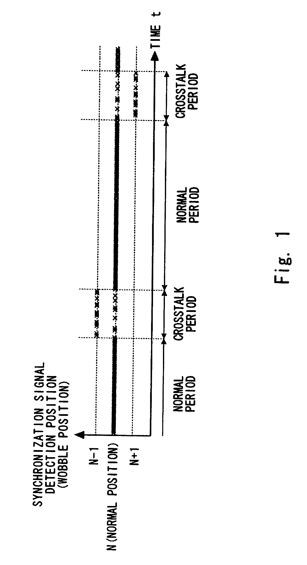
[0065]As a result of extensive study and trial and error on the effect of crosstalk on a synchronization signal detection position (position for detecting a center wobble of an MSK mark) in a case of detecting a synchronization signal (first MSK mark of synchronization blocks) from an MSK-modulated wobble signal, the inventor of the present invention has discovered the following fact.

[0066]In FIG. 1, a symbol “x” denotes a synchronization signal detection position. Note that each detection position indicates a position (wobble pos...


PUM


Abstract

Pseudo synchronization due to crosstalk is detected with a small circuit scale in decoding address information from an MSK-modulated wobble signal. An MSK mark detection unit detects MSK marks periodically placed as synchronization signals in a wobble signal. A first synchronization state determination unit determines synchronization establishment with a detection position of each MSK mark as a reference, or out-of-synchronization. A prediction timing generation unit periodically generates a timing at which each MSK mark is to be detected based on the synchronization position after the establishment of synchronization. A second synchronization state determination unit compares a detection timing with the prediction timing, after the MSK mark is detected at a predetermined position within a period a predetermined number of times in succession, and determines the synchronization position as a pseudo synchronization position due to crosstalk on condition that there is a shift between the detection timing and the prediction timing.

Description

BACKGROUND OF THE INVENTION[0001]1. Field of the Invention[0002]The present invention relates to demodulation of a wobble signal, and more particularly, to a technology for demodulating an MSK (Minimum Shift Keying)-modulated wobble signal.[0003]2. Description of Related Art[0004]There are various standards of optical recording discs (hereinafter, also referred to simply as “disc”) such as DVD+R / RW, DVD-R / RW, DVD-RAM, HD DVD-R / RW / RAM, and BD (Blu-ray Disc)-R / RE. Those discs have a recording film with a groove formed therein along a spiral recording track, for guiding a laser beam. The groove meanders with a frequency and an amplitude that are prescribed in each standard.[0005]The meandering of the groove is called wobbling, and a signal reproduced therefrom is called a wobble signal. In general, in a case of performing a reproducing or recording operation for a disc, a digital wobble signal obtained by subjecting a wobble signal to A / D conversion is multiplied to a prescribed freque...

Claims


Application Information

Patent Timeline
IPC IPC(8): G11B7/007
CPCG11B7/0053
Inventor NAKAGAWA, TAKASHI
Owner RENESAS ELECTRONICS CORP
Why Eureka
Try Eureka