Eureka AIR delivers breakthrough ideas for toughest innovation challenges, trusted by R&D personnel around the world.

System and method for measurung an object location and/or orientation using radio frequency propagation measurements

Inactive Publication Date: 2016-12-08
VAYYAR IMAGING LTD
View PDF2 Cites 4 Cited by
  • Summary
  • Abstract
  • Description
  • Claims
  • Application Information

AI Technical Summary

Benefits of technology

This patent describes a system for controlling a computer device using RF signals. The system includes a controller with an RF transmitting unit that generates unique signals, which are then received by an RF receiving unit. The received signals are analyzed to measure the location and orientation of the controller in a scene. The unique signature can be achieved by modulating the RF signals with a unique frequency, time, or coding scheme. The controller can be attached to a user accessory or embedded in the computer device itself. The system can be used to determine the orientation of objects in space and provides a way to locate and interact with objects using RF signals.

Problems solved by technology

In that scenario, the gestures might include some obstruction of the controllers by other controllers or by other body parts with regard to the system, and might create problem when trying to estimate the movement or the location of the controllers or the body part when there is no line of sight between the controller or the body part and the capturing aperture.
The disadvantage of using accelerometers relates to the drift in the inertial measurement systems, which means that accurate tracking of movement using such devices might be subject to cumulative errors, and might result in error when trying to estimate the position from the movements tracked by such devices.
Using optical point devices might be a problem when the line of sight from the pointing device to the receiving aperture is obstructed by other controllers or by the user's body.

Method used


Image

  • System and method for measurung an object location and/or orientation using radio frequency propagation measurements
  • System and method for measurung an object location and/or orientation using radio frequency propagation measurements
  • System and method for measurung an object location and/or orientation using radio frequency propagation measurements

Examples


Embodiment Construction

[0032]The invention relates to a system, device and method for measuring an object location and / or orientation in space, and more specifically, but not exclusively, to a system, device and method for measuring one or more objects location and orientation in space using multi-RF (Radio Frequency) units.

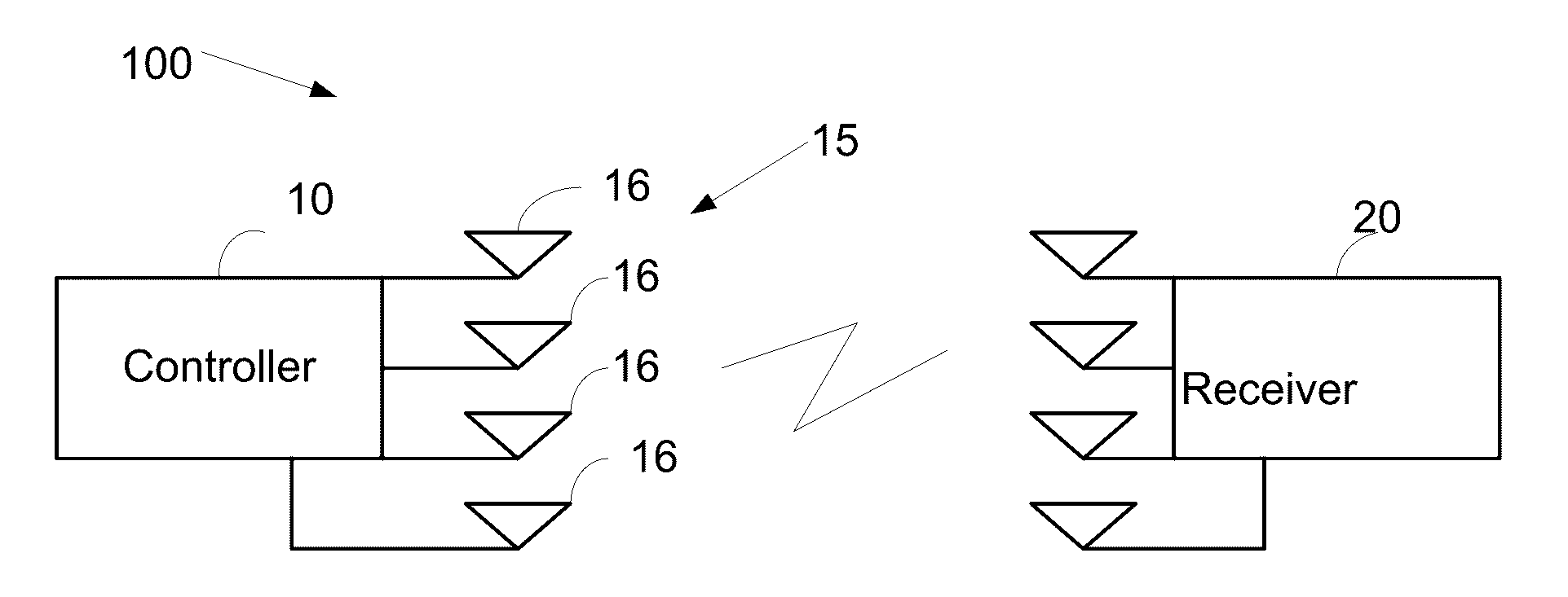
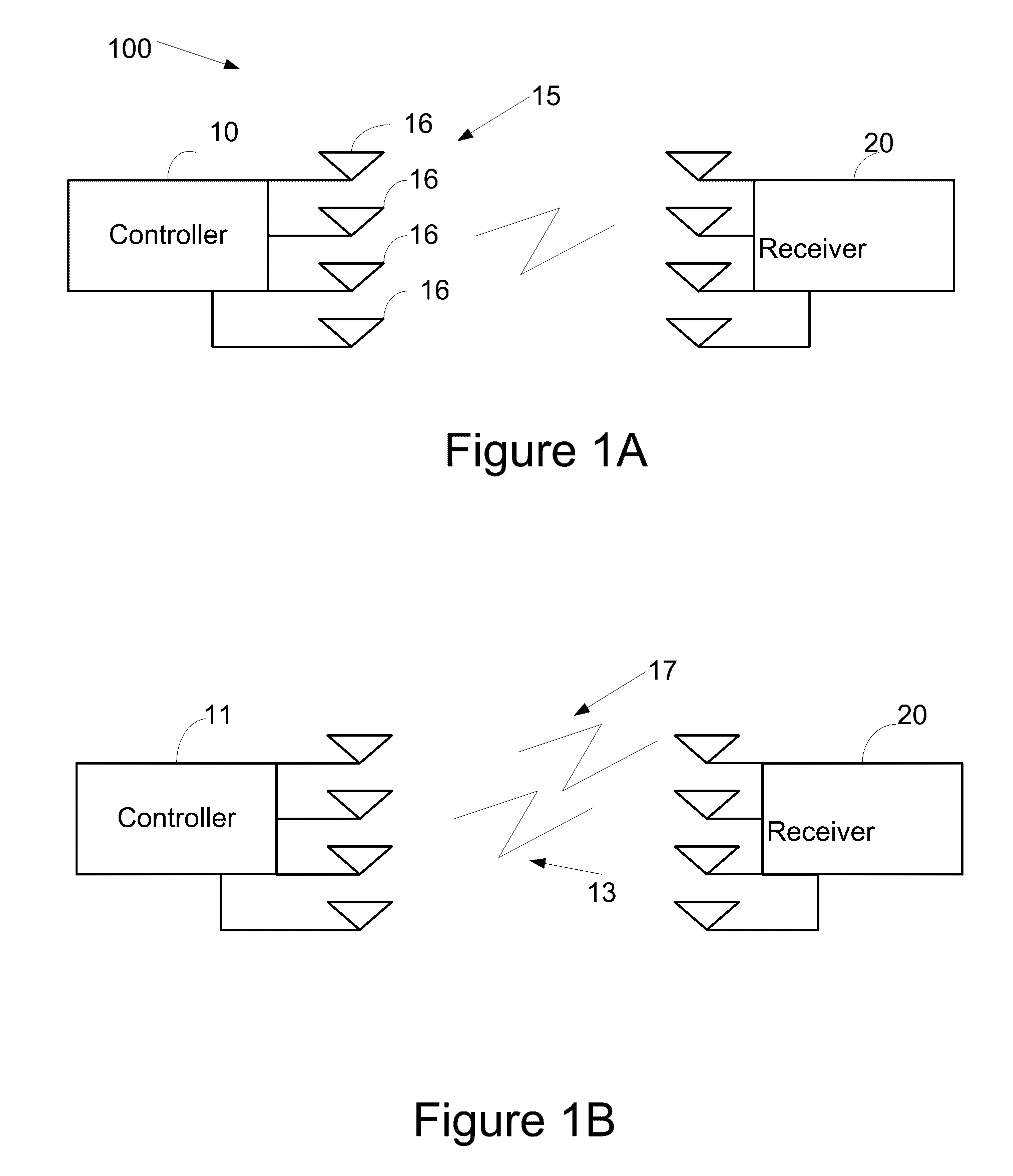
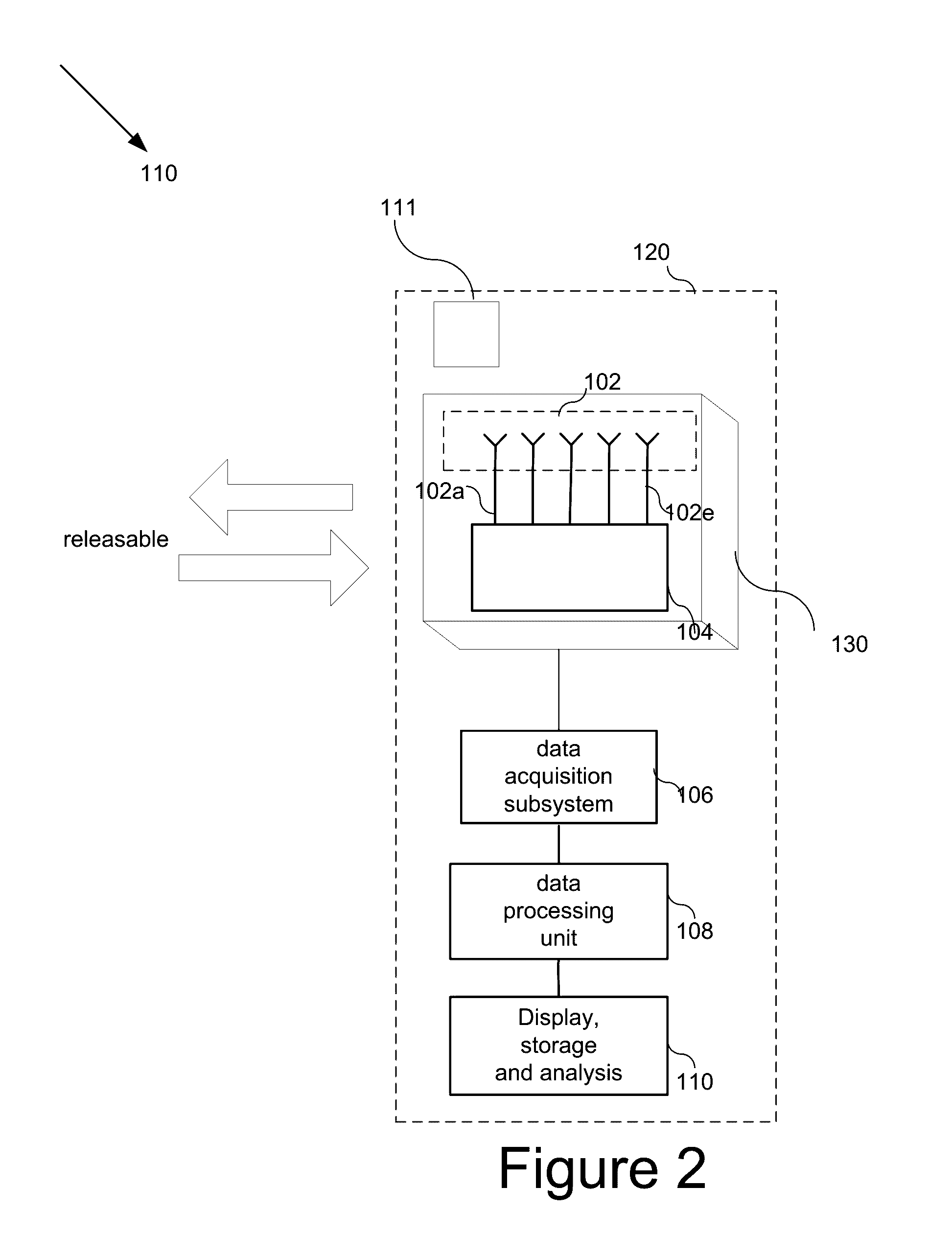
[0033]According to one embodiment, there is provided a system for measuring an object location and / or orientation, comprising: a controller, which comprises a plurality of transmitters or repeaters configured to transmit or repeat RF signals to a receiver. The receiver comprises a plurality of receiving units, such as receiving antennas configured to receive the signals from the controller, and may include a transmitter if the controller is repeating the signal. The system further comprises a processing unit for estimating and measuring the controller location and orientation in space, such as in 3D space.

[0034]Reference is now made to FIG. 1A illustrating a system 100 for measuring an...


PUM


Abstract

The methods, system and device disclosed herein provide a controller for controlling a computer device, the controller comprising a plurality of Radio Frequency (RF) transmitting units or repeating units, the RF transmitting units are configured to generate RF signals the RF signals differ in frequency and / or time and / or coding scheme between said units in a scene; a receiver comprising a plurality of RF receiving units, said RF units are configured to receive reflections of the RF signals; and a computer processor configured to analyze the RF reflected signals and measure the location and / or orientation of the controller in said scene

Description

CROSS-REFERENCE[0001]The present application claims the benefit of U.S. Provisional Application Ser. No. 62 / 171,260, filed on Jun. 5, 2015, entitled “SYSTEM AND METHOD FOR MEASURING AN OBJECT LOCATION AND ORIENTATION USING RF PROPAGATION MEASUREMENTS” (attorney docket no. VY020 / USP), the entire disclosures of which are incorporated herein by reference. The subject matter of the present application is related to PCT Application PCT / IL2015 / 050126, filed Feb. 4, 2015, entitled “SYSTEM DEVISE AND METHOD FOR TESTING AN OBJECT” (attorney docket no. VY005 / PCT), PCT Application PCT / IL2015 / 050099, filed on Jan. 28, 2015, entitled “SENSORS FOR A PORTABLE DEVICE” (attorney docket no. VY003 / PCT), U.S. application Ser. No. 14 / 605,084, filed on Jan. 26, 2015 entitled “VECTOR NETWORK ANALYZER” (attorney docket no. VY001 / US) U.S. application Ser. No. 14 / 499,505, filed on Sep. 30, 2015 entitled “DEVICE AND METHOD FOR CALIBRATING ANTENNA ARRAY SYSTEMS” (attorney docket no. VY002 / US) U.S. application ...

Claims


Application Information

Patent Timeline
IPC IPC(8): G01S5/02G06F3/01
CPCG01S5/0273G06F3/01G01S5/0247G01S5/02G01S5/0226G01S5/06G01S13/878A63F13/216
Inventor MELAMED, RAVIVSHAY, MOSHEHOFFMAN, DAMIANSHAYOVITZ, SHACHARHALIMI, ROHI
Owner VAYYAR IMAGING LTD
Why Eureka
Eureka Blog
Learn More