Imaging lens

a technology of imaging lens and aperture, applied in the field of imaging lens, can solve the problems of increasing the size of imaging lens, limiting the ability of the lens configuration to achieve satisfactory aberration correction, and a large number of lenses, etc., and achieve the effect of satisfactory aberration correction and high resolution

Active Publication Date: 2016-12-08
TOKYO VISIONARY OPTICS CO LTD
View PDF5 Cites 20 Cited by
  • Summary
  • Abstract
  • Description
  • Claims
  • Application Information

AI Technical Summary

Benefits of technology

[0064]According to the imaging lens of the present invention, it is possible to provide the small-sized imaging lens that is ...

Problems solved by technology

However, the increase of the number of lenses easily causes an increase in the size of the imaging lens.
Therefore, the lens configuration having a large number of lenses has a disadvantage in terms of mounting in a small-sized camera such as the above-described smartphones.
In case of the imaging lens of Patent Reference, since a distance from an object-side surface of the first lens to an image plane of an imaging element is long, there is a limit by ...

Method used


Image

  • Imaging lens
  • Imaging lens
  • Imaging lens

Examples


Embodiment Construction

[0083]Hereunder, referring to the accompanying drawings, an embodiment of the present invention will be fully described.

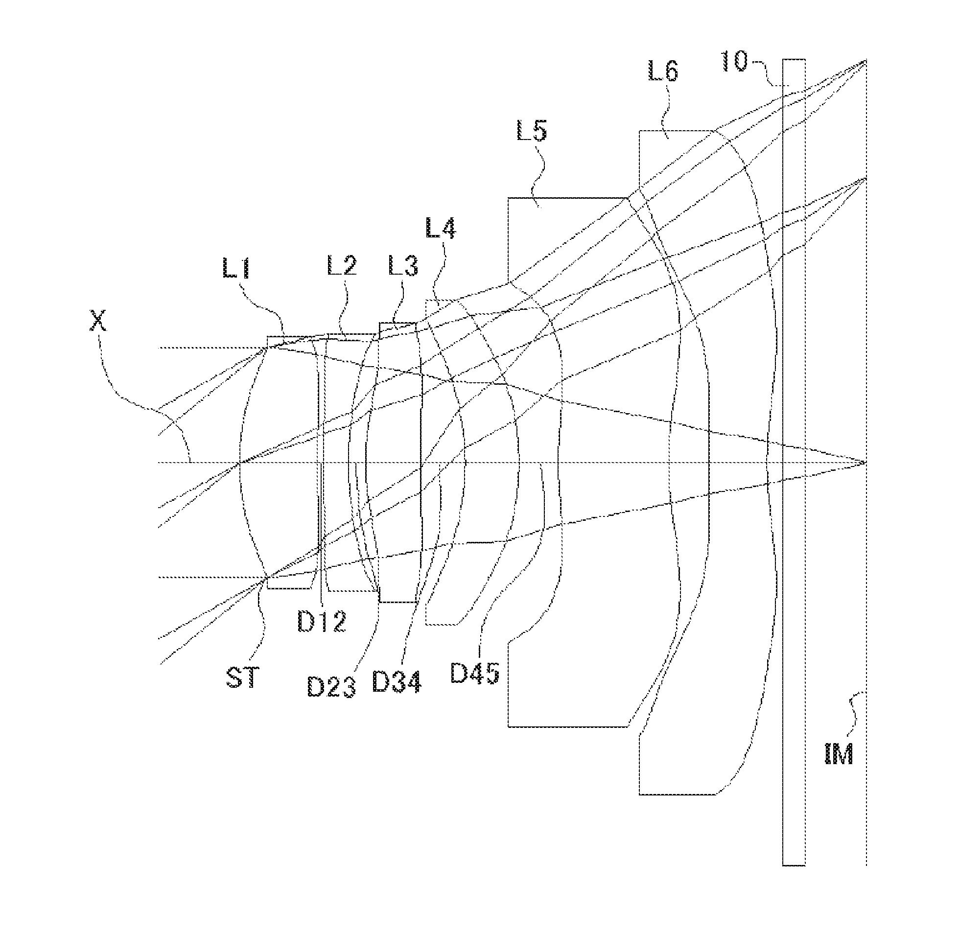
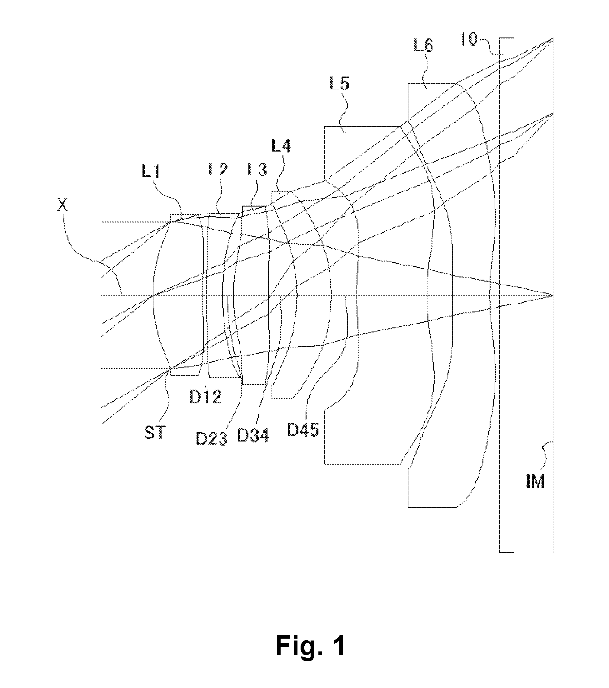
[0084]FIGS. 1, 4, 7, 10, 13, and 16 are schematic sectional views of the imaging lenses in Numerical Data Examples 1 to 6 according to the embodiment, respectively. Since the imaging lenses in those Numerical Data Examples have the same basic configuration, the lens configuration of the embodiment will be described with reference to the illustrative sectional view of Numerical Data Example 1.

[0085]As shown in FIG. 1, according to the embodiment, the imaging lens includes a first lens L1 having positive refractive power, a second lens L2 having negative refractive power, a third lens L3 having positive refractive power, a fourth lens L4 having negative refractive power, a fifth lens L5 having negative refractive power, and a sixth lens L6, arranged in the order from an object side to an image plane side. Between the sixth lens L6 and an image plane IM of an imaging ...


PUM


Abstract

An imaging lens includes a first lens having positive refractive power; a second lens having negative refractive power; a third lens having positive refractive power; a fourth lens; a fifth lens; and a sixth lens, arranged in this order from an object side to an image plane side. The fifth lens is formed in a shape so that a surface thereof on the image plane side has a positive curvature radius. The fifth lens and the sixth lens have a specific composite focal length. The first lens is disposed away from the second lens by a specific distance on an optical axis thereof. The second lens is disposed away from the third lens by a specific distance.

Description

BACKGROUND OF THE INVENTION AND RELATED ART STATEMENT[0001]The present invention relates to an imaging lens for forming an image of an object on an imaging element such as a CCD sensor and a CMOS sensor. In particular, the present invention relates to an imaging lens suitable for mounting in a relatively small camera such as a camera to be built in a cellular phone, a portable information terminal, or the like, a digital still camera, a security camera, a vehicle onboard camera, and a network camera.[0002]In these years, in place of cellular phones that are intended mainly for making phone calls, so-called “smartphones”, i.e., multifunctional cellular phones which can run various application software as well as a voice call function, have been more widely used. When application software is run on smartphones, it is possible to perform functions such as those of digital still cameras and car navigation systems on the smartphones. In order to perform those various functions, most mode...

Claims


Application Information

Patent Timeline
IPC IPC(8): G02B13/00G02B9/62G02B27/00
CPCG02B13/0045G02B9/62G02B27/0025G02B13/18
Inventor KUBOTA, YOJIKUBOTA, KENICHIHIRANO, HITOSHIFUKAYA, HISAO
Owner TOKYO VISIONARY OPTICS CO LTD
Why Eureka
Try Eureka