Fuel tank structure

Inactive Publication Date: 2016-12-15
TOYOTA JIDOSHA KK
View PDF6 Cites 8 Cited by
  • Summary
  • Abstract
  • Description
  • Claims
  • Application Information

AI Technical Summary

Benefits of technology

[0014]In the fuel tank structure of the third aspect, collapsing of the bag-shaped member can be suppressed by the deflation limiting member, and a flow path of the cooling wind can be ensured at the interior of the bag-shaped member.
[0015]As described above, in accordance with the fuel tank structure of the first aspect, there is the excellent effect that a use in pressure of a fuel tank interior, that is due to a rise in the temper

Problems solved by technology

However, the structure of the above-described publication does not consider a rise in the temperature of the fuel tank interior due to

Method used


Image

  • Fuel tank structure
  • Fuel tank structure
  • Fuel tank structure

Examples


Example

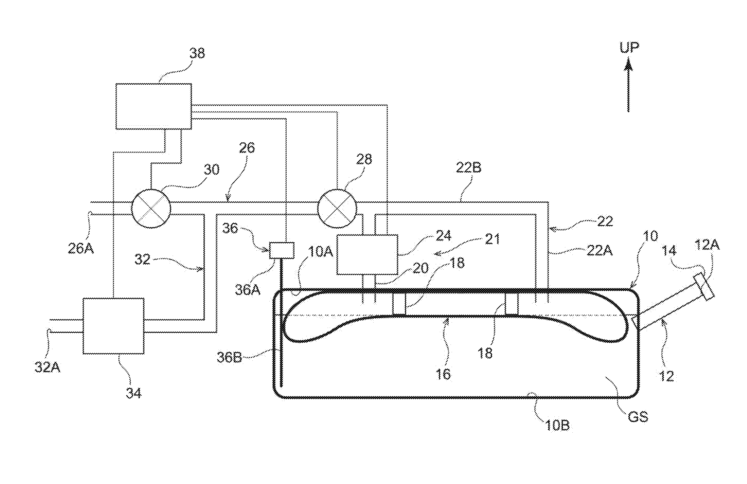
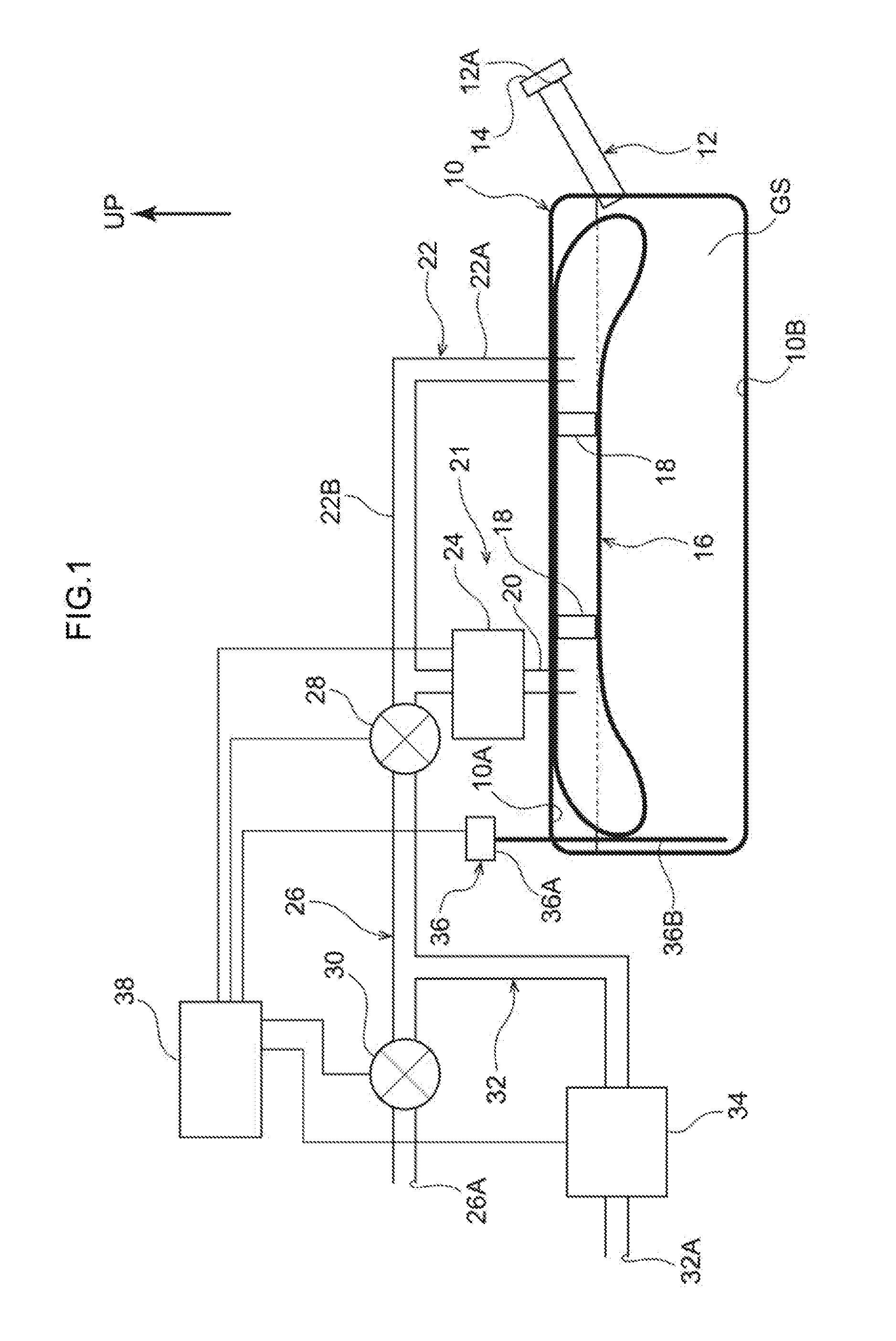
[0023]A fuel tank structure relating to a first embodiment is described hereinafter with reference to FIG. 1 through FIG. 3. Note that arrow UP that is shown appropriately in the respective drawings indicates the upper side of a fuel tank. Further, in the present embodiment, the upper side of the fuel tank and the upper side in the vehicle vertical direction coincide with one another.

[0024]As shown in FIG. 1, a fuel tank 10, that structures the fuel tank structure relating to the present embodiment, is formed in a hollow shape, and is formed in a shape (e.g., the shape of a substantially parallelepiped box) that can accommodate liquid fuel (hereinafter called “fuel GS”) in the interior thereof. Further, the lower surface of the fuel tank 10 is supported by an unillustrated tank band. The fuel tank 10 is mounted to an unillustrated floor panel due to this tank band being fixed to the floor panel via brackets or the like.

[0025]A filler pipe 12 that is substantially tubular is connecte...

Example

Second Embodiment

[0055]A fuel tank structure relating to a second embodiment is described next with reference to FIG. 4. Note that structures that are similar to those of the first embodiment are denoted by the same reference numerals, and description thereof is omitted as appropriate.

[0056]As shown in FIG. 4, in the fuel tank structure relating to the present embodiment, an introducing pipe 52 and a lead-out pipe 54 are connected to the ceiling portion 10A of the fuel tank 10. The introducing pipe 52 is a pipe body for introducing air into the bag-shaped member 16, and extends it the vertical direction. Further, the lower end portion of the introducing pipe 52 is disposed at the interior of the fuel tank 10. On the other hand, the upper end portion of the introducing pipe 52 is connected to a battery chamber 57 that serves as a cooling wind introducing section.

[0057]Here, a battery 58 is installed in the battery chamber 57. A blower 60 for cooling the battery 58 is provided above t...


PUM


Abstract

A fuel tank structure includes: a fuel tank that is installed in an automobile and that accommodates fuel; a bag-shaped member that is fixed to a ceiling portion of an interior of the fuel tank, and whose state of contact with a liquid surface of fuel accommodated in the fuel tank is maintained due to the bag-shaped member inflating or deflating in accordance with a height of the liquid surface; a temperature sensor that senses a temperature of the fuel or evaporated fuel that is within the fuel tank; and a cooling wind introducing section that introduces cooling wind into an interior of the bag-shaped member in a case in which the temperature of the fuel or the evaporated fuel detected by the temperature sensor becomes higher than a predetermined temperature.

Description

CROSS-REFERENCE TO RELATED APPLICATION[0001]This application claims priority under 35 USC 119 from Japanese Patent Application No. 2015-119045 filed Jun. 12 2015, the disclosure of which is incorporated by reference herein.BACKGROUND[0002]Technical Field[0003]The present invention relates to a fuel tank structure.[0004]Related Art[0005]A fuel tank structure, in which an expanding / deflating film that can inflate and deflate is provided within a fuel tank, is disclosed in Japanese Patent Application Laid-Open (JP-A) No. H8-170568 as a fuel tank structure that is installed in an automobile. Further, this JP-A No. H8-170568 discloses a technique in which, by making the pressure within the space that is enclosed by the expanding / deflating film higher than the pressure of fuel vapor, the expanding / deflating film is made to contact the liquid surface of the fuel, and the generation of evaporated fuel is suppressed.SUMMARY[0006]However, the structure of the above-described publication does ...

Claims


Application Information

Patent Timeline
IPC IPC(8): B60K15/03G01N25/00
CPCB60K15/03G01N25/00B60K2015/03217B60K2015/0321B60K2015/03414B60K2015/03072B60K2015/03078B60K2015/03085
Inventor ASO, SHUICHI
Owner TOYOTA JIDOSHA KK
Why Eureka
Try Eureka