Screw compressors

A screw compressor, compression chamber technology, applied in mechanical equipment, machines/engines, liquid fuel engines, etc., can solve problems such as heightening and shortening the life of structural components

Active Publication Date: 2017-04-12
HITACHI IND EQUIP SYST CO LTD
View PDF1 Cites 0 Cited by
  • Summary
  • Abstract
  • Description
  • Claims
  • Application Information

AI Technical Summary

Problems solved by technology

[0003] If the pressure of the working fluid temporarily rises as described above, there will be problems such as high pressure acting on structural components such as the two rotors and shortening the life of the structural components.

Method used


Image

  • Screw compressors
  • Screw compressors
  • Screw compressors

Examples


Embodiment 1

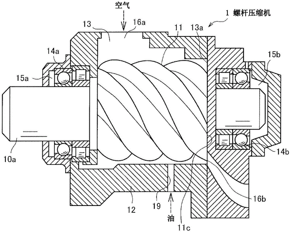
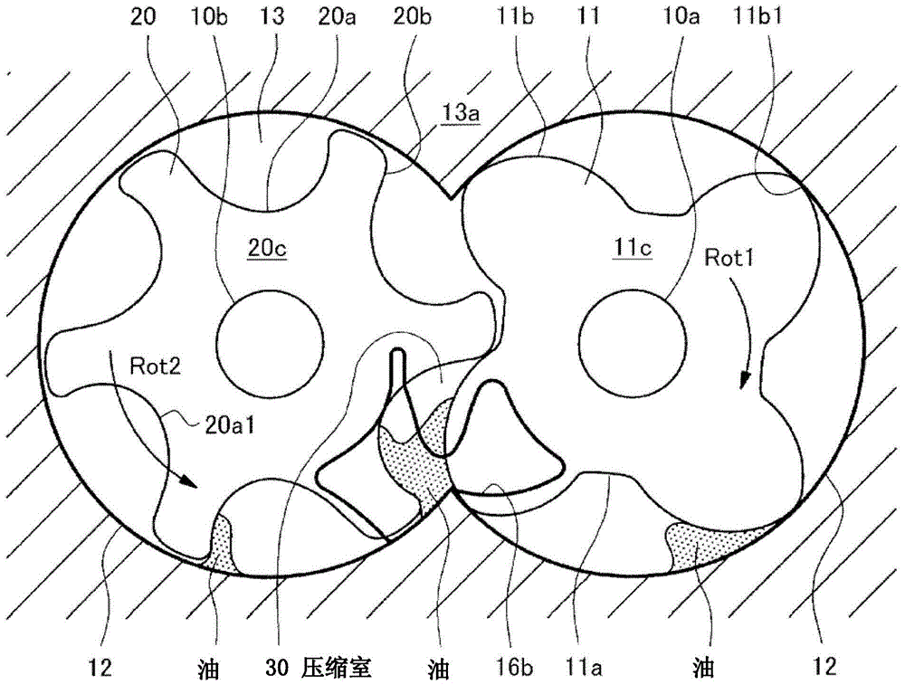
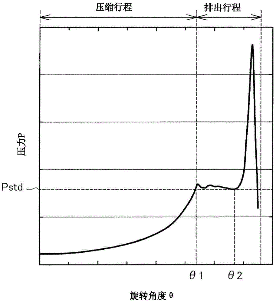
[0025] figure 1 It is a sectional view showing the structure of the screw compressor according to Embodiment 1 of the present invention. also, figure 2 It is the figure which observed the 1st rotor and the 2nd rotor of the conventional shape from the discharge end surface side, image 3 is a graph showing the pressure change in the compression chamber. also, Figure 4 (a) is a figure which shows the oil storage part formed in the tooth part of a 1st rotor, (b) is a perspective view of an oil storage part. also, Figure 5 It is a figure which shows the state which the compression chamber disappeared.

[0026] Such as figure 1 , figure 2 As shown, the screw compressor 1 of Embodiment 1 compresses a working fluid by using the first rotor 11 (male rotor) and the second rotor 20 (female rotor) rotating in mesh with each other. and if figure 2 As shown, the rotation direction Rot1 of the first rotor 11 is opposite to the rotation direction Rot2 of the second rotor 20 . ...

Embodiment 2

[0065] Figure 8 (a) is a figure which shows the oil storage part of Example 2, (b) is a perspective view of an oil storage part.

[0066] In addition, the screw compressor equipped with the first rotor and the second rotor of Embodiment 2 is the same as figure 1 , figure 2 The screw compressor 1 of the illustrated embodiment 1 has the same structure. Therefore, the same structural elements as those of the screw compressor 1 of Embodiment 1 are attached with figure 1 , figure 2 The same symbols are used and detailed explanations are omitted.

[0067] Such as Figure 8 As shown in (a) and (b), the tooth portion 20b of the second rotor 20 in Embodiment 2 is provided with a second concave portion (second oil storage portion 23) instead of the first oil storage portion formed on the first rotor 11. 22 (see Figure 4 (a)).

[0068] The second oil storage portion 23 formed on the second rotor 20 of the second embodiment is formed by orienting the axial end surface 20c of the...


PUM


Abstract

The invention provides a screw compressor as a subject which can suppress disappearance of a compressed working fluid and pressure rise in discharging. The screw compressor of the invention comprises a first rotor (11) and a second rotor (20) which are engaged with each other and rotate to compress the working fluid. Air is compressed as a compression chamber (30) formed by engagement between the first rotor (11) and the second rotor (20) shrinks. The compression chamber (30) shrinks until the compression chamber (30) disappears. Furthermore, the screw compressor is characterized in that a recessed first oil storing portion (22) forms in an axial end surface (11c) of a tooth portion (11b) of the first rotor (11); the first oil storing portion (22) is communicated with a working chamber (13) or the compression chamber (30) through a first opening portion (22a) forming in a tooth top (11b1) of the tooth portion (11b); the first opening portion (22a) is at a position where the tooth top (11b1) of the tooth portion (11b) is superposed with a tooth bottom (20a1) of a tooth groove (20a) when the compression chamber (30) disappears.

Description

technical field [0001] The present invention relates to screw compressors. Background technique [0002] In a screw compressor in which a pair of rotors (a male rotor and a female rotor) engage and rotate to compress a working fluid, the two rotors are supplied with working oil for lubrication and cooling. The supplied working oil moves to the discharge end face together with the compressed working fluid, and is discharged from the discharge port. At this time, the discharge port is temporarily blocked by the working oil, preventing the working fluid from being discharged from the discharge port. Therefore, the pressure of the working fluid temporarily becomes high. [0003] If the pressure of the working fluid temporarily increases as described above, high pressure acts on structural components such as the two rotors, shortening the life of the structural components. [0004] As a technique to solve this problem, Patent Document 1 describes: "A recess that can temporaril...

Claims


Application Information

Patent Timeline
Patent Type & Authority Patents(China)
IPC IPC(8): F04C18/16F04C29/00
CPCF04C18/16F04C2240/20
Inventor 千叶纮太郎土屋豪太田广志高野正彦頼金茂幸
Owner HITACHI IND EQUIP SYST CO LTD
Why Eureka
Try Eureka