Liquid jetting apparatus

a technology of liquid jetting and apparatus, which is applied in the field of liquid jetting apparatus, can solve the problems of high cost, increase in the size of the apparatus, and leakage of pressure to the exterior, and achieve the effect of suppressing an excessive increase in pressure, raising the cost of the apparatus, and not increasing the siz

Active Publication Date: 2012-01-10
BROTHER KOGYO KK
View PDF7 Cites 0 Cited by
  • Summary
  • Abstract
  • Description
  • Claims
  • Application Information

AI Technical Summary

Benefits of technology

[0007]However, in the abovementioned positive-pressure purge operation for the ink tank having the positive-pressure control valve, when the positive pressure for the purge is supplied to the ink tank and the pressure inside the tank is increased, the positive-pressure control valve opens the atmosphere opening hole, and the pressure is leaked to an exterior through the atmosphere opening hole. When the pressure is leaked, since sufficient positive pressure is not propagated from the ink tank to the nozzle hole of the jetting head, there arises a need to use a high pressure pump for the pump which supplies the positive pressure for purge, which causes an increase in a size of the apparatus, and a high cost.
[0008]In view of this, an object of the present invention is to provide a positive-pressure purge function without increasing the size and the cost of the apparatus, while suppressing an excessive increase in the pressure inside a liquid storage chamber.

Problems solved by technology

However, in the abovementioned positive-pressure purge operation for the ink tank having the positive-pressure control valve, when the positive pressure for the purge is supplied to the ink tank and the pressure inside the tank is increased, the positive-pressure control valve opens the atmosphere opening hole, and the pressure is leaked to an exterior through the atmosphere opening hole.
When the pressure is leaked, since sufficient positive pressure is not propagated from the ink tank to the nozzle hole of the jetting head, there arises a need to use a high pressure pump for the pump which supplies the positive pressure for purge, which causes an increase in a size of the apparatus, and a high cost.

Method used


Image

  • Liquid jetting apparatus
  • Liquid jetting apparatus
  • Liquid jetting apparatus

Examples


first embodiment

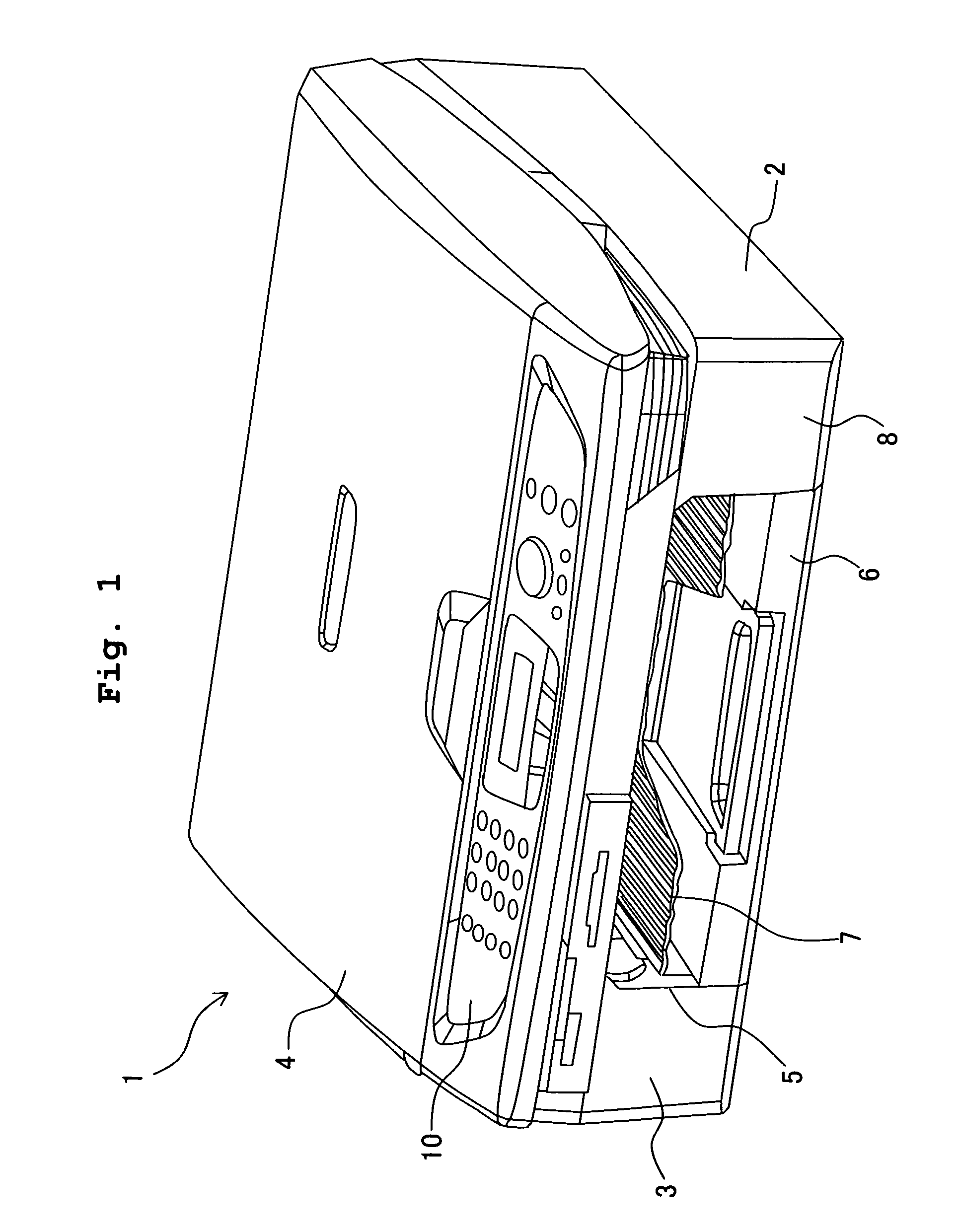
[0059]FIG. 1 is a perspective view showing a multi-function device 1 having an ink-jet recording apparatus 3 (liquid jetting apparatus) according to a first embodiment of the present invention. The multi-function device 1 has a printer function, a scanner function, a copy function, and a facsimile function. As shown in FIG. 1, the multi-function device 1 has a casing 2, the ink-jet recording apparatus 3 for printing which is positioned at a lower portion of the casing 2, as well as a scanner unit 4 which is positioned at an upper portion of the casing 2. An opening 5 is formed in a front face of the casing 2. Two trays 6 and 7 are positioned in a stacked manner in the opening 5. In other words, a paper feeding tray 6 of the ink-jet recording apparatus 3 is provided at a lower stage in the opening 5, and a paper discharge tray 7 of the ink-jet recording apparatus 3 is provided at an upper stage (upper stand) of the opening 5. On a bottom-right portion of a front-face side of the ink-...

second embodiment

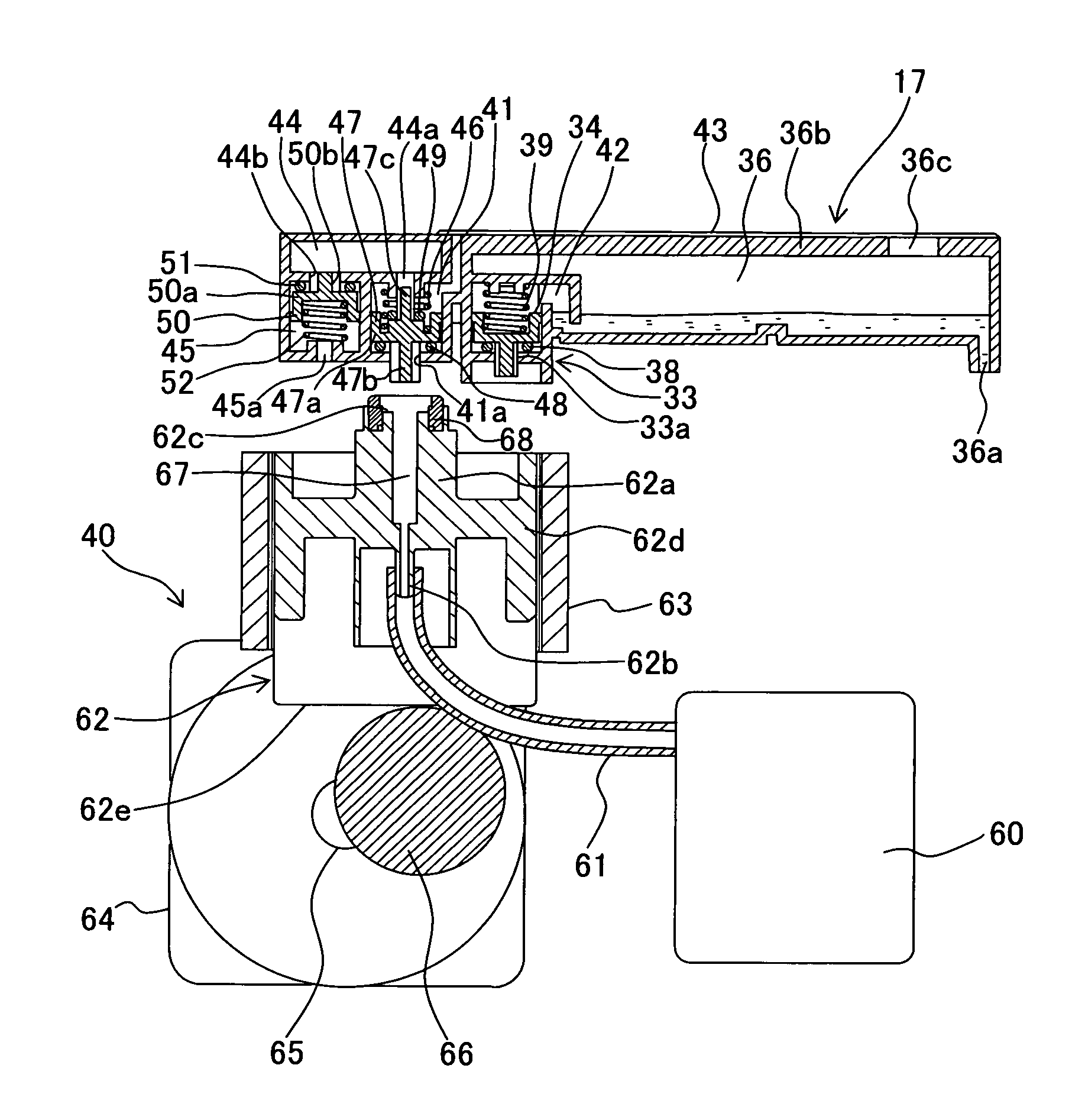
[0086]Next, a second embodiment will be described below. FIG. 1 is a cross-sectional view showing a state in which a combination valve 147 of the second embodiment of the present invention is at a ‘first position’. A point of difference from the first embodiment is that a seal member 149 which closes (blocks) the communicating hole 44a is different. Same reference numerals are assigned to components having the same structure as in the first embodiment, and the description thereof is omitted. As it is shown in FIG. 7, a communicating port 136c is formed in an upper wall portion 136b of an ink storage tank 136 of a sub tank 117 of the second embodiment. A labyrinth channel 136d having a meander shape in a plan view is formed as a groove, on an upper surface of the upper wall portion 136b. One end portion of the labyrinth channel 136d communicates with the communicating port 136c and the other end portion of the labyrinth channel 136d communicates with the gas distributing chamber 41.

[...


PUM


Abstract

A liquid jetting apparatus includes: a head; an ink storage chamber communicating with the head; a gas distributing chamber in which a gas introducing hole is formed; a buffer chamber in which a communicating hole for communicating with the gas distributing chamber, and an atmosphere opening hole for opening to the atmosphere are formed; a combination valve which is capable of opening and closing the gas introducing hole and the communicating hole; a gas introducing mechanism which introduces the compressed air through the gas introducing hole to the head to jet the ink forcibly, and a positive-pressure control valve which opens the atmosphere opening hole when a pressure in the buffer chamber exceeds a predetermined value. It is possible to operate a positive-pressure purge while suppressing an excessive increase in the pressure inside the liquid storage chamber, without increasing a size and a cost of the apparatus.

Description

CROSS REFERENCE TO RELATED APPLICATION[0001]The present application claims priority from Japanese Patent Application No. 2006-356904, filed on Dec. 29, 2006, the disclosure of which is incorporated herein by reference in its entirety.BACKGROUND OF THE INVENTION[0002]1. Field of the Invention[0003]The present invention relates to a liquid jetting apparatus such as an ink-jet recording apparatus which records an image on a recording medium by jetting an ink from a jetting head.[0004]2. Description of the Related Art[0005]For example, in an ink-jet recording apparatuses described in Japanese Patent Application Laid-open No. H5-92578, when a viscosity of an ink in a nozzle hole of a jetting head is increased due to not using the apparatus for a long time, or when there is a blocking of the nozzle hole due to mixing of an impurity etc., a positive-pressure purge operation is carried out. In the positive-pressure purge operation, an inside of an ink tank which communicates with the jettin...

Claims


Application Information

Patent Timeline
Patent Type & Authority Patents(United States)
IPC IPC(8): B41J2/19B41J2/17B41J2/175
CPCB41J2/17596
Inventor YAMADA, TAKAHIROOKAZAKI, NAOYASHIMIZU, YOICHIROSOMEYA, MASARU
Owner BROTHER KOGYO KK
Why Eureka
Try Eureka