Superconducting magnet device
A superconducting magnet and superconducting technology, applied in superconducting magnets/coils, superconducting parts, measuring devices, etc., can solve problems such as volume increase and internal temperature rise
- Summary
- Abstract
- Description
- Claims
- Application Information
AI Technical Summary
Problems solved by technology
Method used
Image

Examples
Embodiment approach 1
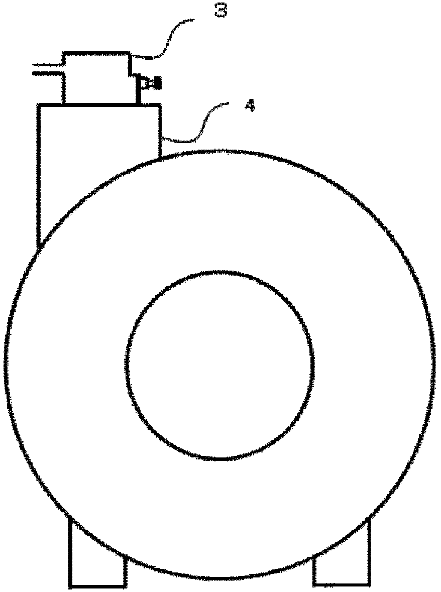
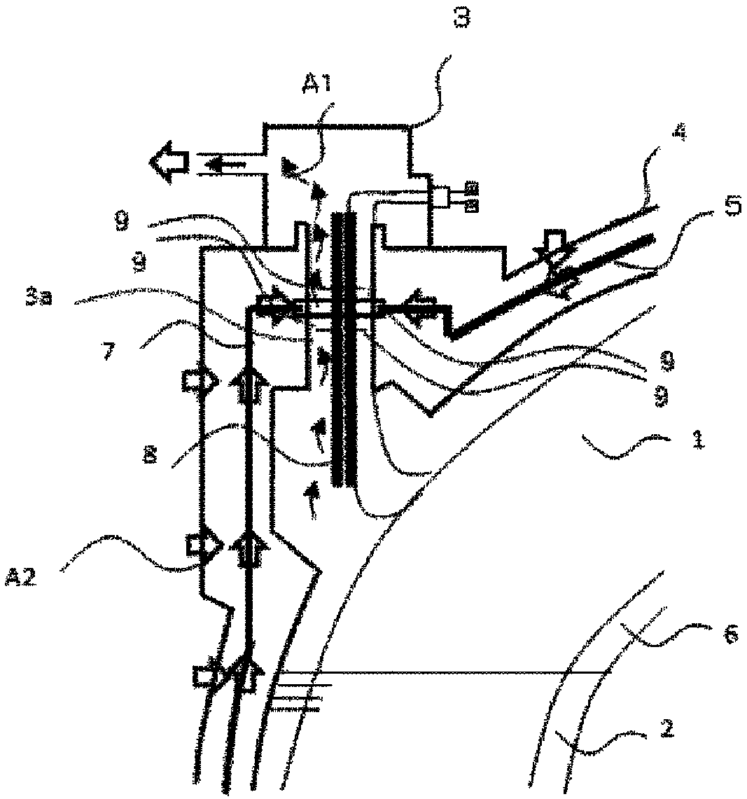
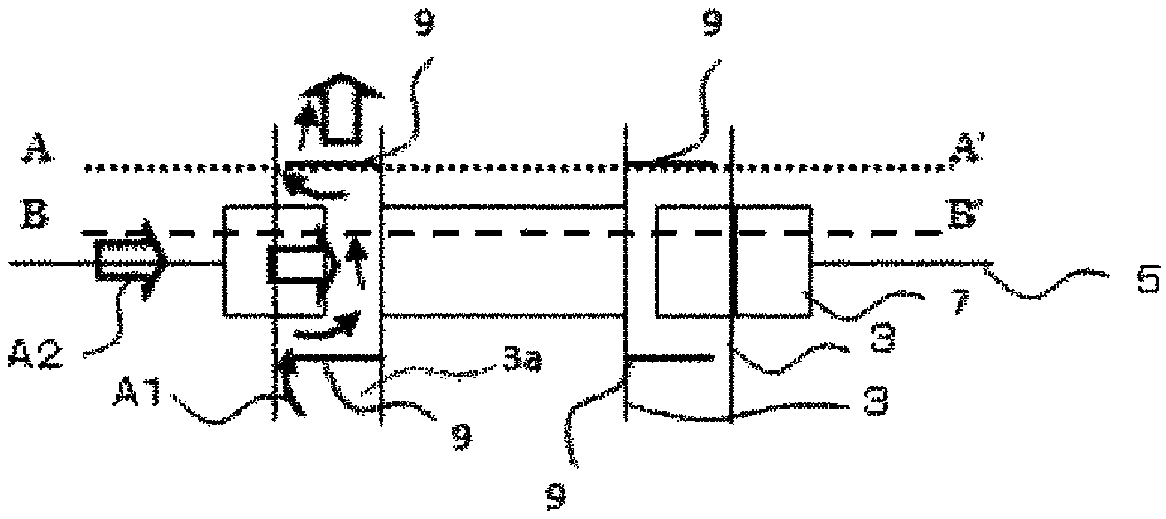
[0045] use Figure 1 to Figure 6 , the superconducting electromagnet device according to Embodiment 1 of the present invention will be described. figure 1 is a schematic diagram of a superconducting electromagnet setup. figure 2 as well as image 3 is a vertical sectional view of the superconducting electromagnet device. Figure 4 It is viewed from above to below in the vertical direction image 3 The top view of the A-A' section in . Figure 5 It is viewed from above to below in the vertical direction image 3 The top view of the BB' section in . Image 6 is a vertical cross-sectional view when rapid cooling occurs. In addition to showing the Figures 15-16In addition to the structure of the conventional superconducting electromagnet shown, a helium gas exhaust pipe 3 a , a heat transfer member 7 , and a convection preventing device described later are shown as one of the characteristic components in Embodiment 1 of the present invention. 9 and the structure of thei...
Embodiment approach 2
[0061] use Figure 7 to Figure 10 , a superconducting electromagnet device according to Embodiment 2 of the present invention will be described. Figure 7 is the vertical sectional view, Figure 8 yes Figure 7 The top view of the C-C' section datum in Figure 9 show Figure 7 The DD’ section in Figure 10 A vertical cross-sectional view at the time of rapid cooling is shown. In addition to showing the Figure 15 , Figure 16 , Figure 17 In addition to the structure of the conventional superconducting electromagnet shown, a helium gas exhaust pipe 3 a , a heat transfer member 7 , and a convection preventing device described later are shown as one of the characteristic components in Embodiment 2 of the present invention. 9 and their surrounding structures. Description of the same configuration as in Embodiment 1 is omitted.
[0062] The superconducting electromagnet device includes a superconducting coil 1, liquid helium 2, helium exhaust pipe 3a, vacuum container 4, ...
Embodiment approach 3
[0070] use Figure 11 to Figure 14 , Embodiment 3 of the present invention will be described. Figure 11 is the vertical sectional view, Figure 12 yes Figure 11 The top view of the E-E' section datum in Figure 13 show Figure 11 The F-F' section in Figure 14 A vertical cross-sectional view at the time of rapid cooling is shown. In addition to showing the Figure 15 , Figure 16 , Figure 17 In addition to the structure of the conventional superconducting electromagnet device shown, the helium gas exhaust pipe 3a, the heat transfer member 7, and the convection prevention member, which are one of the characteristic components in Embodiment 3 of the present invention, are also shown. 9 and the structures surrounding them.
[0071] The superconducting electromagnet device is equipped with a conventional structure such as superconducting coil 1, liquid helium 2, helium gas exhaust pipe 3a, vacuum container 4, heat shield 5, heat transfer member 7, and electrode 8, and a...
PUM
| Property | Measurement | Unit |
|---|---|---|
| thickness | aaaaa | aaaaa |
Abstract
Description
Claims
Application Information