
Containerized system and method for spray evaporation of water

a containerized system and water technology, applied in the direction of evaporation, separation process, evaporation regulation/control, etc., can solve the problems of reducing slow removal of water by solar-evaporation or spray ponds, and complex energy-intensive processes. achieve the effect of optimizing the evaporation rate of undesired water, reducing and optimizing the size of water droplets

Inactive Publication Date: 2016-12-15
ENERGY WATER SOLUTIONS LLC
View PDF15 Cites 24 Cited by
  • Summary
  • Abstract
  • Description
  • Claims
  • Application Information

AI Technical Summary

Benefits of technology

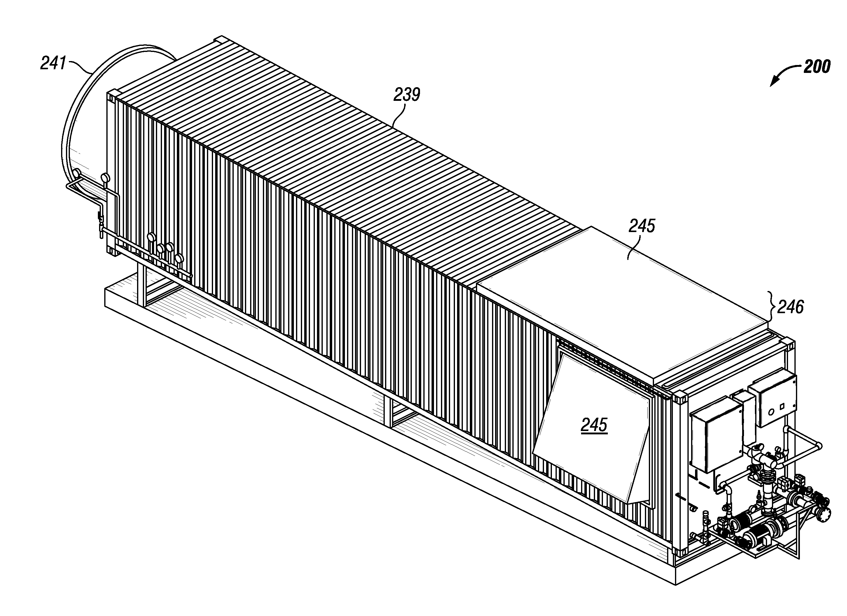
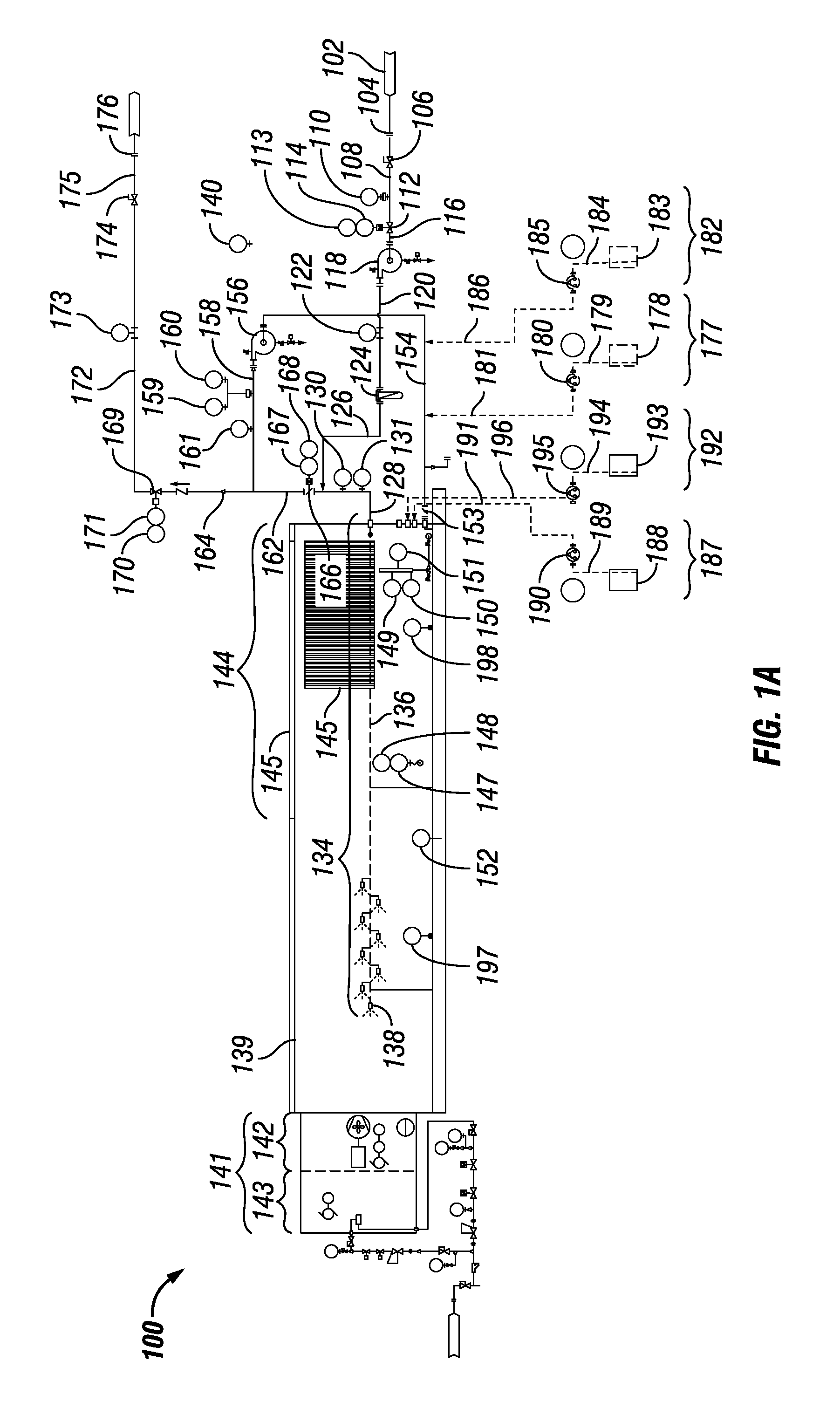
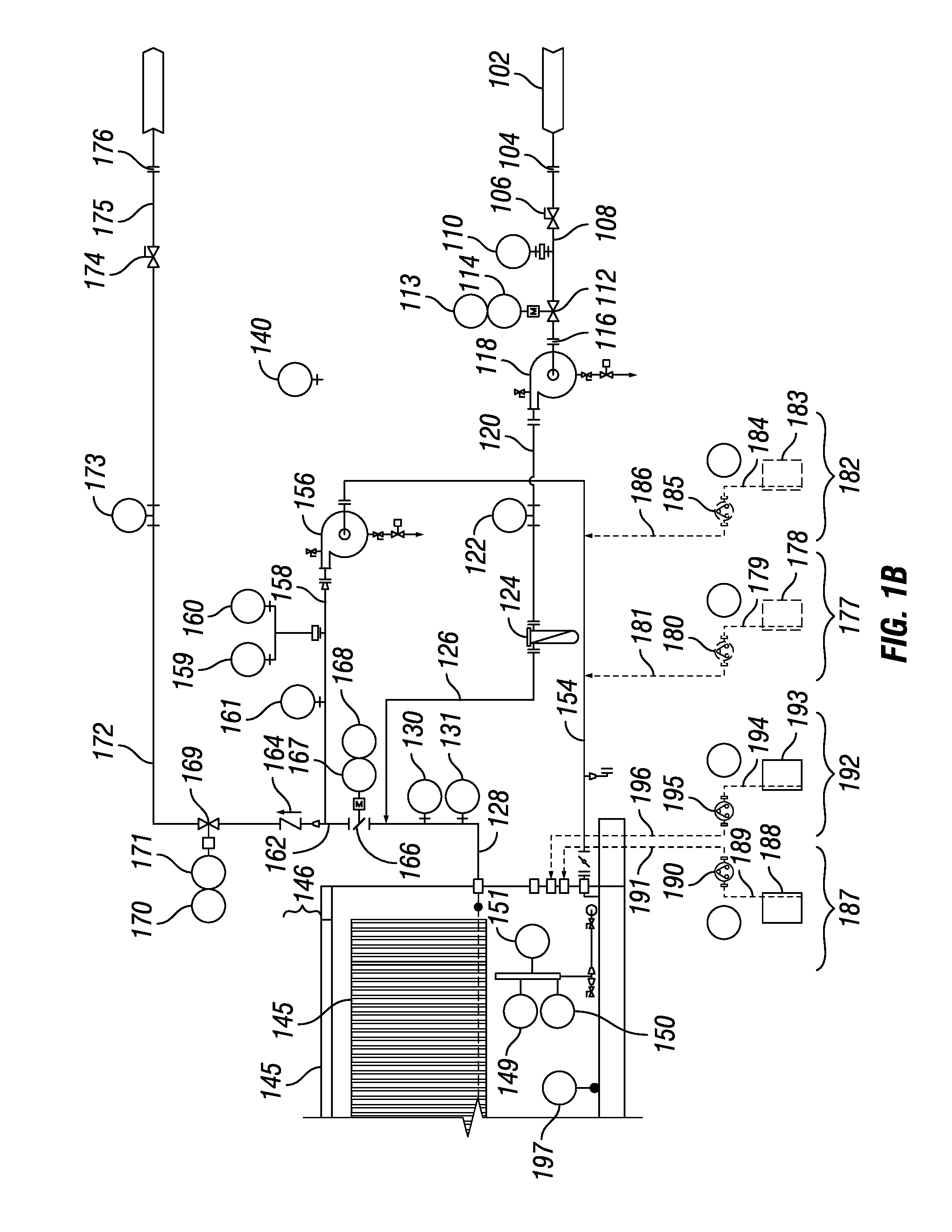
The invention is a system and method for efficient spray evaporation of water by controlling pump pressure and water droplet size sprayed within a closed container. The system maximizes the evaporation rate of un-desired water by reducing water droplet size sprayed within the container and optimizing water droplet size and volume sprayed within the container. The evaporated water exits the container as water vapor through a mist arresting system and can be stored or disposed of. The system includes a wastewater inlet, pumps, a container, a spray nozzle, an air blower, an air heater, and a programmable logic controller. The system can also include an acid conditioning system, a bactericide conditioning system, a scale inhibition conditioning system, and a defoamer system. The technical effects of the invention include efficient spray evaporation of water, reduced water droplet size, and minimized water droplet size.

Problems solved by technology

These methods have numerous problems.
The large surface area solar-evaporation or spray ponds are slow to remove water.
MSF is a complex energy intensive process with high resultant operating costs.
This can be quite expensive.

Method used


Image

  • Containerized system and method for spray evaporation of water
  • Containerized system and method for spray evaporation of water
  • Containerized system and method for spray evaporation of water

Examples


Embodiment Construction

[0060]The following detailed description of various embodiments of the present invention references the accompanying drawings, which illustrate specific embodiments in which the invention can be practiced. While the illustrative embodiments of the invention have been described with particularity, it will be understood that various other modifications will be apparent to and can be readily made by those skilled in the art without departing from the spirit and scope of the invention. Accordingly, it is not intended that the scope of the claims appended hereto be limited to the examples and descriptions set forth herein but rather that the claims be construed as encompassing all the features of patentable novelty which reside in the present invention, including all features which would be treated as equivalents thereof by those skilled in the art to which the invention pertains. Therefore, the scope of the present invention is defined only by the appended claims, along with the full sc...


PUM


Abstract

A system for spray evaporating water comprising: a wastewater inlet; a pump, where an outlet of the wastewater inlet is fluidly connected to an inlet of the pump and wherein an outlet of the pump is fluidly connected to an inlet of a manifold; a spray nozzle, wherein an outlet of the manifold is fluidly connected to an inlet of the spray nozzle; a container, wherein an upper portion of the container is enclosed with a demister element and wherein the outlet of the spray nozzle discharges into the container; and a discharge outlet, wherein a bottom of the container is fluidly connected to the discharge outlet. A method of spray evaporating water is also disclosed.

Description

PRIOR RELATED APPLICATIONS[0001]This application claims benefit of U.S. Provisional Patent Application Ser. No. 62 / 173,509, filed on Jun. 10, 2015, entitled “Containerized System and Method for Spray Evaporation of Water.”FEDERALLY SPONSORED RESEARCH STATEMENT[0002]Not Applicable (N / A)REFERENCE TO MICROFICHE APPENDIX[0003]N / AFIELD OF INVENTION[0004]The invention relates generally to spray evaporation of water and, in particular, to a containerized system and method for spray evaporation of water by controlling pump pressure and / or water droplet size sprayed within a closed container by optimizing water volumetric flow and droplet size sprayed within the container.BACKGROUND OF THE INVENTION[0005]Current methods for evaporation of undesired water (e.g., landfill leachate, produced water, mining wastewater, and wastewater) typically involve large surface area ponds, floating or land-based atomizing sprayers which spray back into a pond, or multi-stage flash evaporation (MSF). These me...

Claims


Application Information

Patent Timeline
IPC IPC(8): C02F1/12B01D1/00B01D1/30C02F5/08C02F1/04C02F1/50C02F1/00C02F1/66B01D1/20B01D1/14
CPCC02F1/12C02F2209/006B01D1/0082B01D1/305B01D1/14C02F1/048C02F1/042C02F1/50C02F1/008C02F1/66C02F5/08C02F2209/02C02F2209/06C02F2209/05C02F2209/38C02F2209/40C02F2303/04B01D1/20C02F2201/005C02F2209/005C02F2209/008C02F2209/03C02F2303/12C02F2303/22C02F2303/26B01D1/16B01D19/04Y02A20/212B05B1/00B05B1/26Y02W10/37
Inventor SHINER, STEPHEN M.HANEBUTH, CHUCK
Owner ENERGY WATER SOLUTIONS LLC
Learn More