Compact containerized system and method for spray evaporation of water

a containerized system and water spray technology, applied in the direction of evaporation, separation process, evaporation regulation/control, etc., can solve the problems of large capital investment, slow water removal of surface area solar-evaporation or spray pond, and numerous methods, and achieve efficient spray evaporation of water

Active Publication Date: 2019-10-03
ENERGY WATER SOLUTIONS LLC
View PDF19 Cites 7 Cited by
  • Summary
  • Abstract
  • Description
  • Claims
  • Application Information

AI Technical Summary

Benefits of technology

[0007]The invention relates generally to spray evaporation of water and, in particular, to a compact containerized system and method for efficient spray evaporation of water by controlling pump pressure and / or water droplet size sprayed within a closed container and by optimizing water volumetric flow and droplet size sprayed within the container

Problems solved by technology

These methods have numerous problems.
The large surface area solar-evaporation or spray ponds are slow to remove water, require large capital investments, and pose a risk of leakage.
MSF is a complex energy intensive process with high resultant capital and operating costs as well as problematic air emissions.
This can be quite expensive.

Method used


Image

  • Compact containerized system and method for spray evaporation of water
  • Compact containerized system and method for spray evaporation of water
  • Compact containerized system and method for spray evaporation of water

Examples


first alternative embodiment

[0810]A flow diagram for a method 800 of using a first alternative system for spray evaporation of water is shown in FIGS. 8A-8B. In an embodiment, the method 800 comprises selecting predetermined parameters (e.g., air flow rate, air heating rate, maximum conductivity, maximum humidity, maximum pH, minimum air temperature, minimum pH, water flow rate, water droplet size) for a system for spray evaporation of water, drawing wastewater into the system from an external water source using a pump, diverting the wastewater to a spray nozzle, spraying the wastewater through the spray nozzle to create water droplets, blowing the water droplets and air into a container of the system using an air blower, collecting condensed water in the sump (bottom) of the container, recycling condensed water from the bottom of the container using the pump, and diverting the concentrated waste to a waste outlet, as illustrated in FIGS. 8A-8B.

[0811]In an embodiment, the method 800 comprises a step 802 of sel...

second alternative embodiment

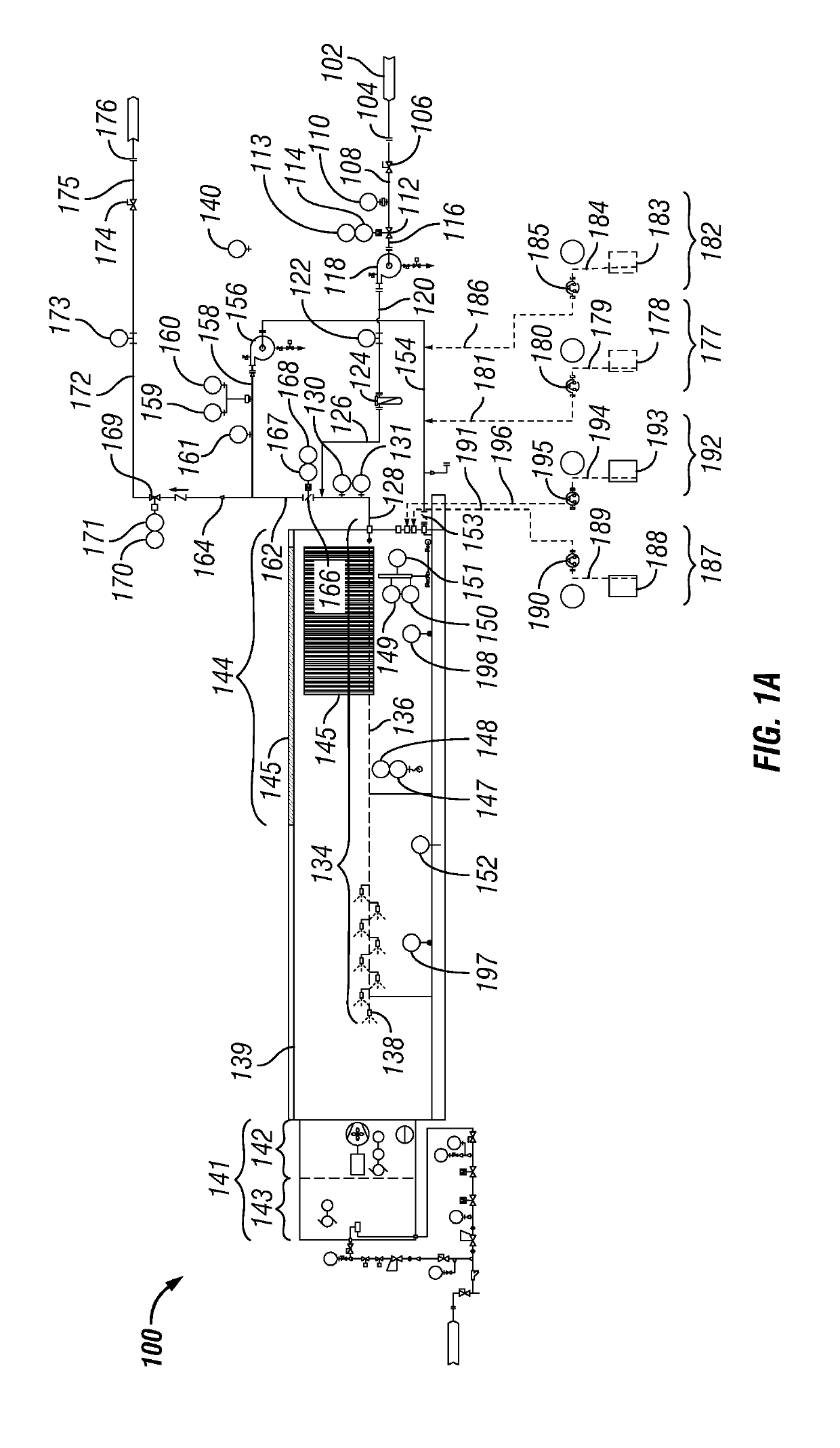
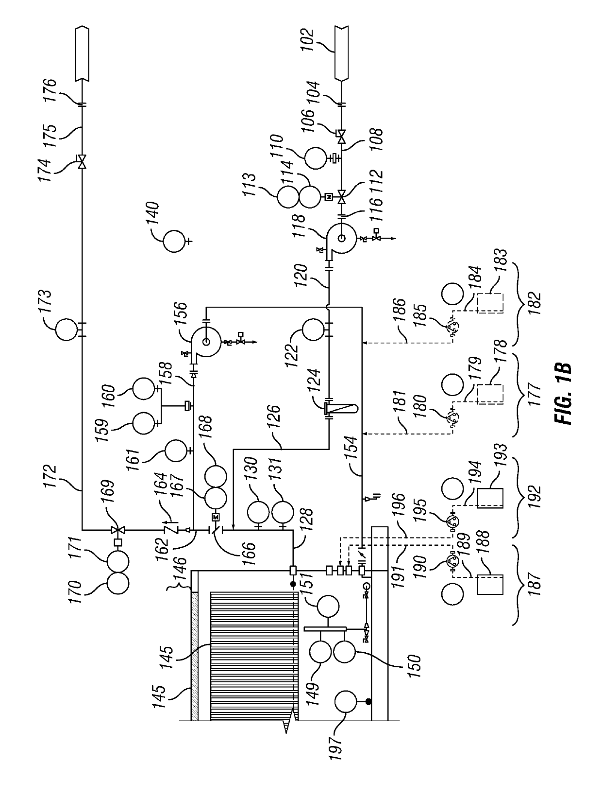
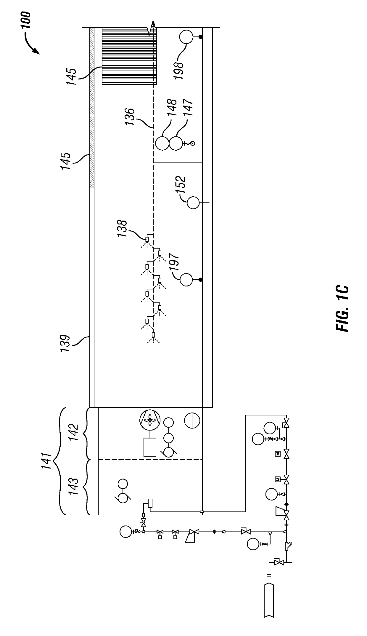
[0849]A flow diagram for a method 1200 of using a second alternative system for spray evaporation of water is shown in FIGS. 12A-12B. In an embodiment, the method 1200 comprises selecting predetermined parameters (e.g., air flow rate, air heating rate, ambient temperature, discharge air temperature, maximum conductivity, maximum humidity, maximum pH, minimum air temperature, minimum pH, total suspended solids, volatile organic carbon (VOC), water flow rate at feed inlet, water flow rate at discharge outlet, water droplet size) for a system for spray evaporation of water, drawing wastewater into the system from an external water source using a pump, diverting the wastewater to a manifold, a drip system, a packing system or a tray system, flowing the wastewater or water droplets over the packing system or the tray system disposed within a container of the system, blowing air into the container counter to flow of the wastewater or the water droplets from the drip system using an air bl...


PUM

PropertyMeasurementUnit
temperaturesaaaaaaaaaa
water droplet sizesaaaaaaaaaa
air heating rateaaaaaaaaaa

Abstract

A wastewater evaporation system for spray evaporating water comprising: a wastewater feed inlet; a pump, wherein an outlet of the wastewater inlet is fluidly connected to an inlet of the pump and wherein an outlet of the pump is fluidly connected to an inlet of a manifold; a drip orifice, wherein an outlet of the manifold is fluidly connected to an inlet of the drip orifice; a container, wherein an upper portion of the container is enclosed with a demister element; a packing system and/or a tray system disposed within the container, wherein the outlet of the drip orifice discharges water droplets onto the packing system and/or the tray system; a discharge outlet, wherein a bottom of the container is fluidly connected to the discharge outlet; and an air system comprising an air blower and optionally an air preheater, wherein the air system is disposed through a wall of the container and wherein the air system discharges air flow counter to the water droplets from the drip orifice. A method of spray evaporating water while limiting emission of particles regulated as pollutants is also disclosed.

Description

PRIOR RELATED APPLICATIONS[0001]This application is a continuation-in-part of U.S. Nonprovisional patent application Ser. No. 15 / 177,519, filed on Jun. 9, 2016, which claims benefit of U.S. Provisional patent application Ser. No. 62 / 173,509, filed on Jun. 10, 2015, entitled “Containerized System and Method for Spray Evaporation of Water.”FEDERALLY SPONSORED RESEARCH STATEMENT[0002]Not Applicable (N / A)REFERENCE TO MICROFICHE APPENDIX[0003]N / AFIELD OF INVENTION[0004]The invention relates generally to spray evaporation of water and, in particular, to a containerized system and method for spray evaporation of water by controlling pump pressure and / or water droplet size sprayed within a closed container by optimizing air and water volumetric flow and droplet size sprayed within the container.BACKGROUND OF THE INVENTION[0005]Current methods for evaporation of undesired water (e.g., landfill leachate, produced water, mining wastewater, and wastewater) typically involve large surface area p...

Claims


Application Information

Patent Timeline
Patent Type & Authority Applications(United States)
IPC IPC(8): B01D1/14B01D1/00B01D1/20B01D1/30B01D19/04B05B1/26C02F1/00C02F1/04C02F1/12C02F1/50C02F1/66C02F5/08
CPCC02F1/008B01D1/20C02F2209/008C02F2209/40C02F2209/006C02F2303/22C02F2303/26B01D1/0082C02F2209/03B01D1/14C02F1/66C02F2209/06C02F2209/38C02F2303/12C02F2303/04B05B1/26C02F5/08B01D19/04C02F1/12C02F2209/02C02F1/042C02F1/50C02F2209/05C02F1/048B01D1/305C02F2201/005B01D1/16B01D5/006B01D5/009Y02W10/37
Inventor SHINER, STEPHEN M.HANEBUTH, CHUCK
Owner ENERGY WATER SOLUTIONS LLC
Why Eureka
Try Eureka