
Alignment apparatus and method

a technology of alignment apparatus and shaft, applied in the direction of measuring devices, using electrical means, instruments, etc., can solve the problems of reducing affecting the accuracy of alignment, and destroying the ultimate damage of couplings, etc., to prolong the overall life, increase the reliability of machines, and achieve quick and accurate positioning. the effect of accurate and fast machine alignmen

Active Publication Date: 2016-12-15
AB SKF
View PDF13 Cites 3 Cited by
  • Summary
  • Abstract
  • Description
  • Claims
  • Application Information

AI Technical Summary

Benefits of technology

The present invention offers an improved alignment system with a live view to help users quickly achieve accurate positioning. The system has a built-in reporting function to show when the alignment is achieved and can be shared for reference keeping or for operator driven reliability programs. The system is suitable for both basic and advanced shaft alignment, increasing reliability and reducing maintenance costs. It uses mobile devices that intuitively guide users through the whole alignment process. The system targets the core alignment tasks and is designed to be a very easy-to-use instrument. It also uses inductive proximity sensors to afford accurate and reliable shaft alignment for every budget.

Problems solved by technology

Correct shaft alignment is very important for the machines, as misalignment causes vibration and additional forces that damage the machine components such as, bearings, seals, couplings and foundation bolts.
Contrary, any misalignment, even minimal, can lead to vibration, excessive wear, and ultimate destruction of couplings, bearings, seals, gears and other components.
Even flexible couplings that are designed to withstand minor misalignments cannot prevent negative effects on other machine components.
Field experience shows that around 50% of machine breakdowns can be attributed to damage resulting from shaft misalignment.
Straight edges or Eyesight, which are fast and easy methods but not accurate.
Dial gauges which allow high accuracy but are complicated to use.
To the extent effective, the aforementioned prior art devices are complicated to use, bulky, and expensive to manufacture and service.

Method used


Image

  • Alignment apparatus and method
  • Alignment apparatus and method
  • Alignment apparatus and method

Examples


Embodiment Construction

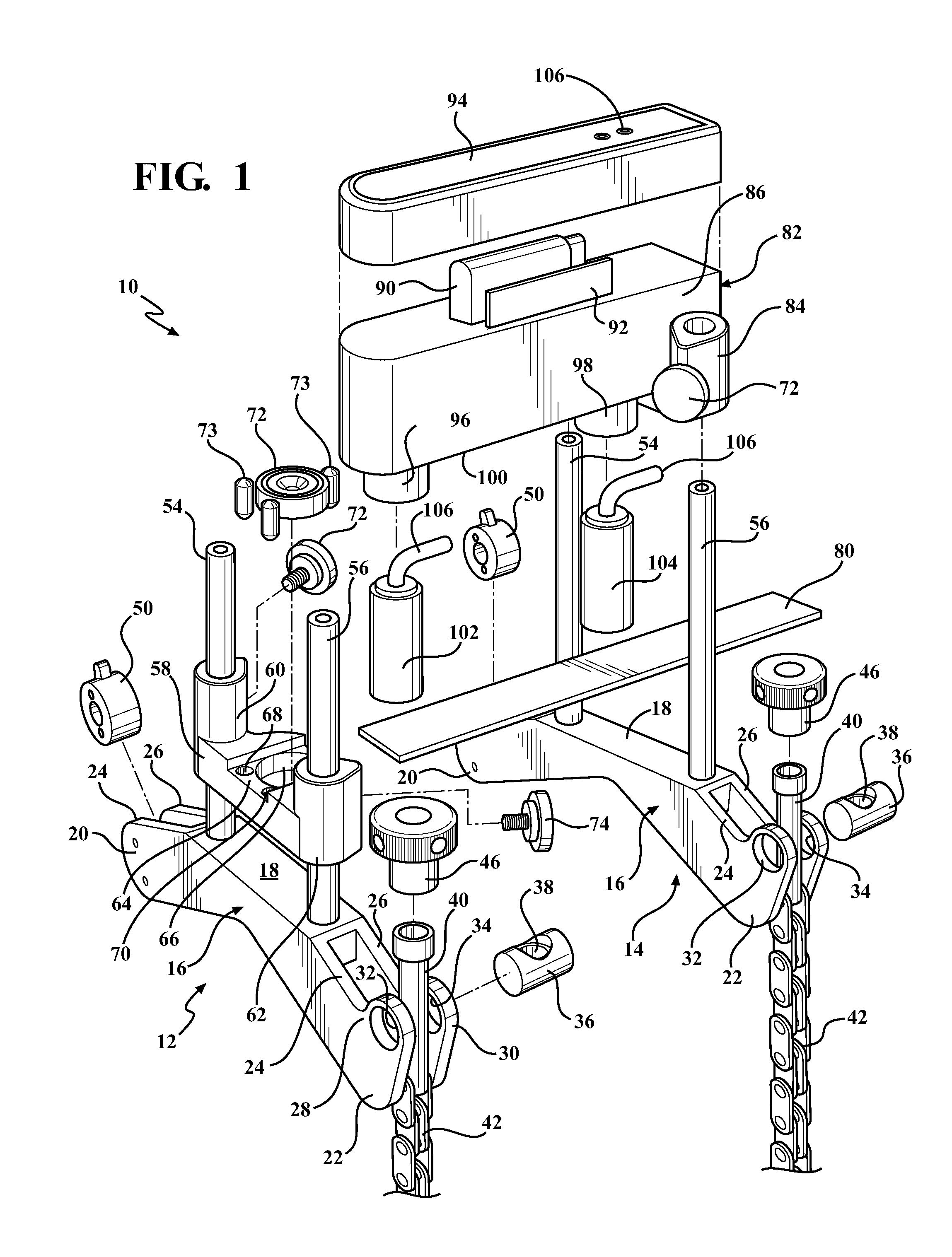
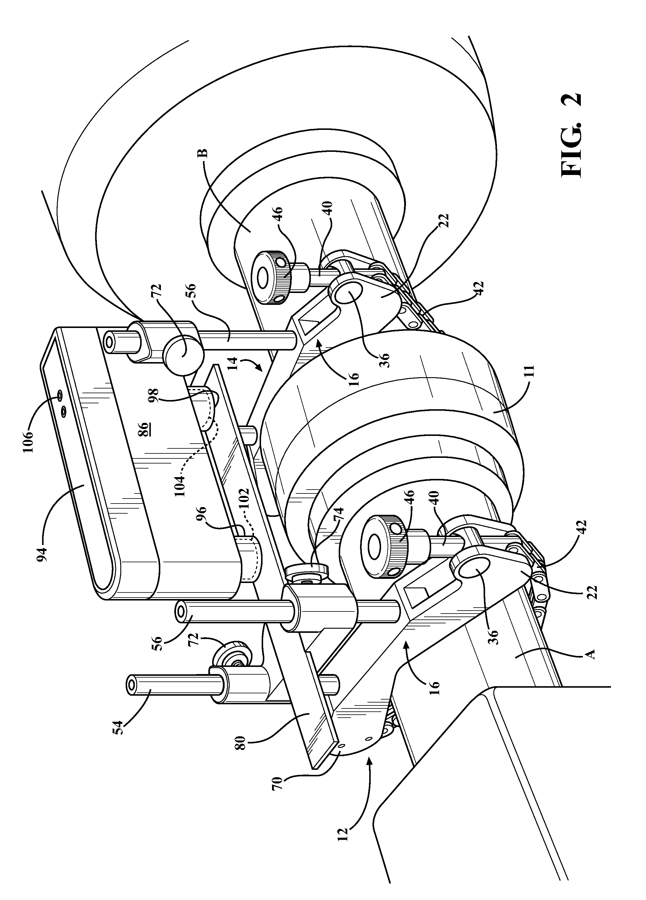
[0035]Referring to the Figures, wherein like numerals indicate like or corresponding parts throughout the several views, an alignment apparatus (the tool) of the present invention is generally shown at 10 in FIGS. 1 through 5. FIGS. 2 through 4 illustrate the tool 10 mounted to a pair of shafts A and B connected by a coupling 11 having two parts, with one of the shafts A extending from a compressor C and the other shaft B extending from a motor M. The compressor C and the motor M are used for exemplary purposes and are not intended to limit the scope of the present invention. The tool 10 can be used on any other types of equipment that have rotatable shafts.

[0036]When perfectly aligned, such shafts A and B have their axes of rotation thereby coinciding along a straight line, generally indicated at L in FIG. 4. Contrary, any misalignment, as shown in FIG. 3, even minimal, can lead to vibration, excessive wear, and ultimate destruction of couplings, bearings, seals, gears and other co...


PUM


Abstract

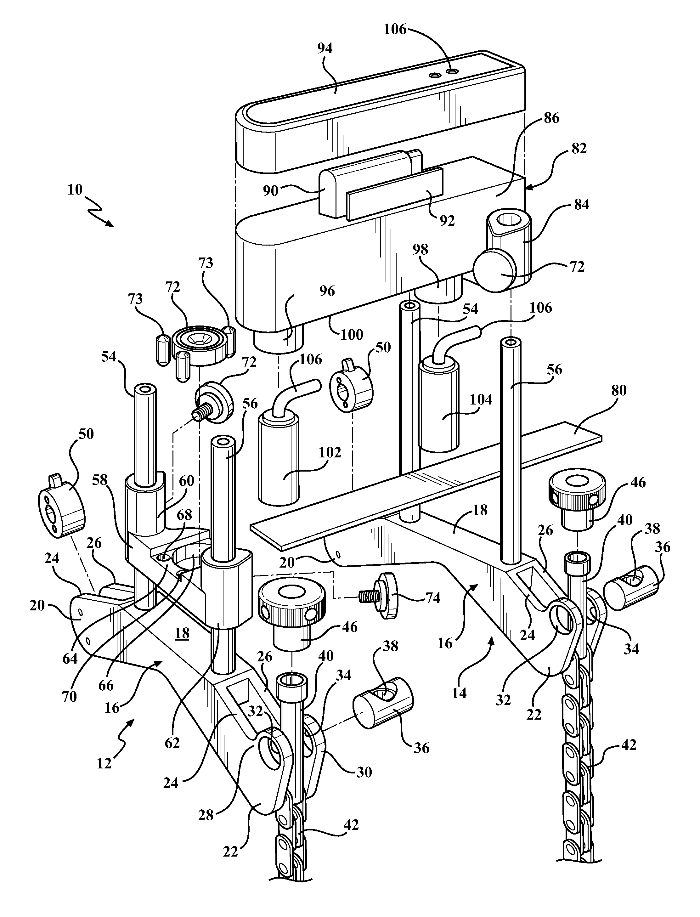
An alignment apparatus (the tool) of the present invention includes a pair of bracket devices for rigidly holding shafts. As the shafts are secured to the bracket devices with chains, sensors of one of the bracket devices are exposed to an extension beam of the other bracket device thereby defining gaps or distances between the extension beam and the sensors. If offset is determined between the distances because one shaft is misaligned relative the other shaft, the sensors send signal to a mobile device, thereby informing a user about misalignment between the shafts.

Description

FIELD OF THE INVENTION[0001]The present invention relates generally to apparatus and method for aligning shafts and other parts which are coupled together, and more particularly to the apparatus and method to determine misalignment between the shafts in order to properly align the shafts.BACKGROUND OF THE INVENTION[0002]As known to those skilled in the art, it is very important that the shafts be aligned within predetermined tolerances when two rotating machine shafts are coupled together, such as, for example, the shaft of an electric motor and the shaft of a pump. Shaft alignment is recommended for almost every industry, as it enables machine uptime to be significantly improved and maintenance costs to be reduced. Correct shaft alignment is very important for the machines, as misalignment causes vibration and additional forces that damage the machine components such as, bearings, seals, couplings and foundation bolts.[0003]When perfectly aligned, such shafts have their axes of rot...

Claims


Application Information

Patent Timeline
Patent Type & Authority Applications(United States)
IPC IPC(8): G01B5/25
CPCG01B5/25G01B7/31G01B11/27
Inventor ANDERSSON, NILS OLOF TORBJORNANDERSSON, THOMAS EIVIND
Owner AB SKF
Learn More