Wrap around antenna

Active Publication Date: 2016-12-15
COMMSCOPE TECH LLC
View PDF13 Cites 26 Cited by
  • Summary
  • Abstract
  • Description
  • Claims
  • Application Information

AI Technical Summary

Benefits of technology

[0005]Various aspects of the present disclosure may be directed to a base station antenna comprising an antenna assembly. The antenna assembly may comprise a plurality of

Problems solved by technology

Due to real estate constraints, the top of the support structure is often not available.
And mounting the antenna offset to a side of the support structure may not be desirable.
For example, antennas offset to the side of the support structure may not be aesthe

Method used


Image

  • Wrap around antenna
  • Wrap around antenna
  • Wrap around antenna

Examples


Embodiment Construction

will be better understood when read in conjunction with the appended drawings. For the purpose of illustrating the disclosure, there are shown in the drawings embodiments which are presently preferred. It should be understood, however, that the disclosure is not limited to the precise arrangements and instrumentalities shown.

[0007]In the drawings:

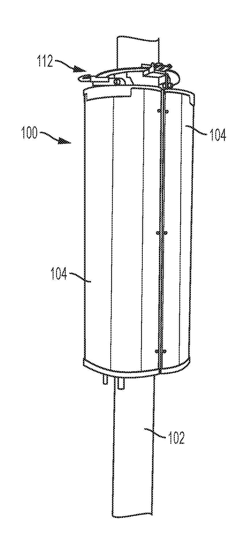
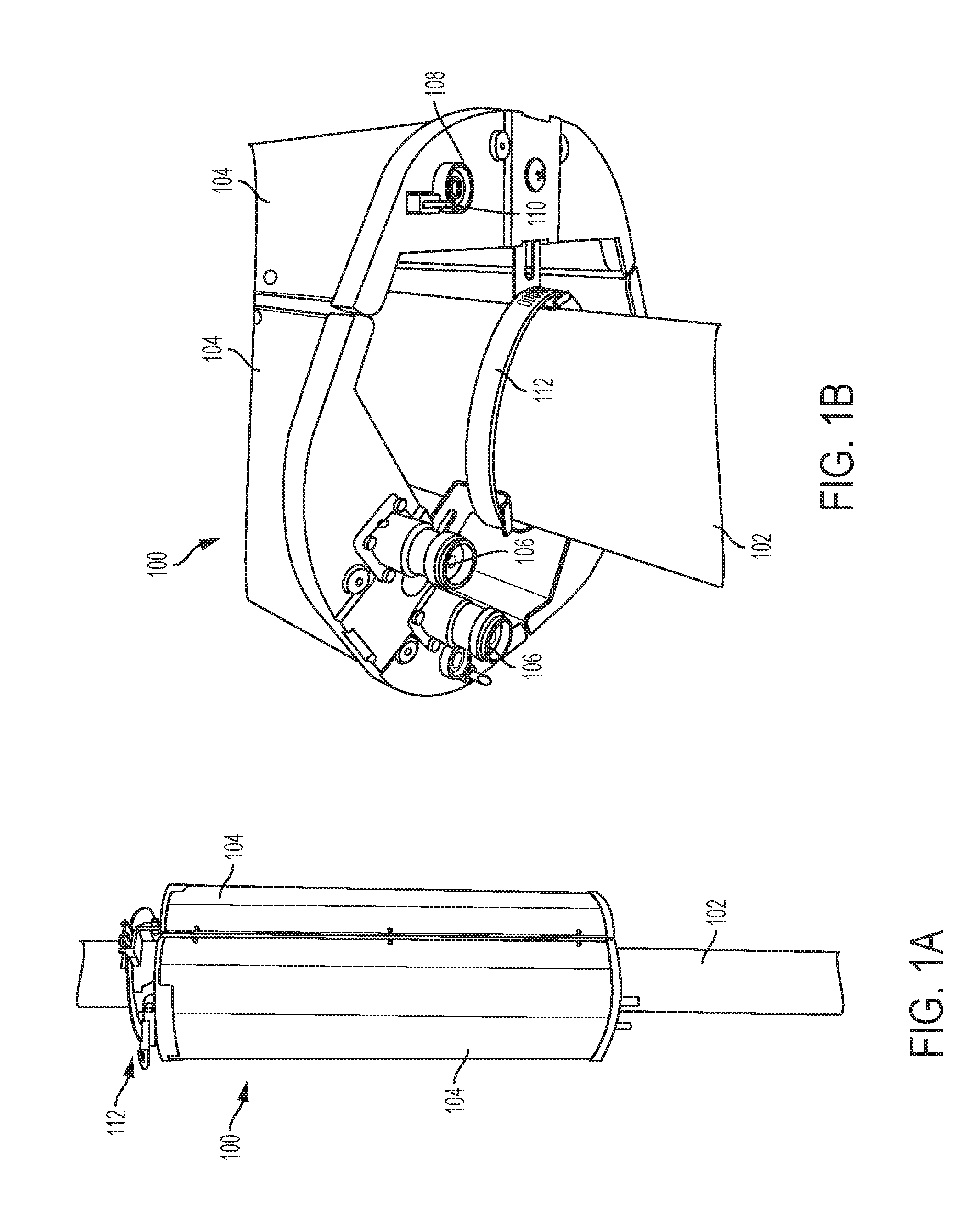
[0008]FIG. 1A is a perspective view of a side of a wrap-around antenna encircling a support structure, according to an aspect of the present disclosure;

[0009]FIG. 1B is a perspective view of an underside of the wrap-around antenna, according to an aspect of the present disclosure;

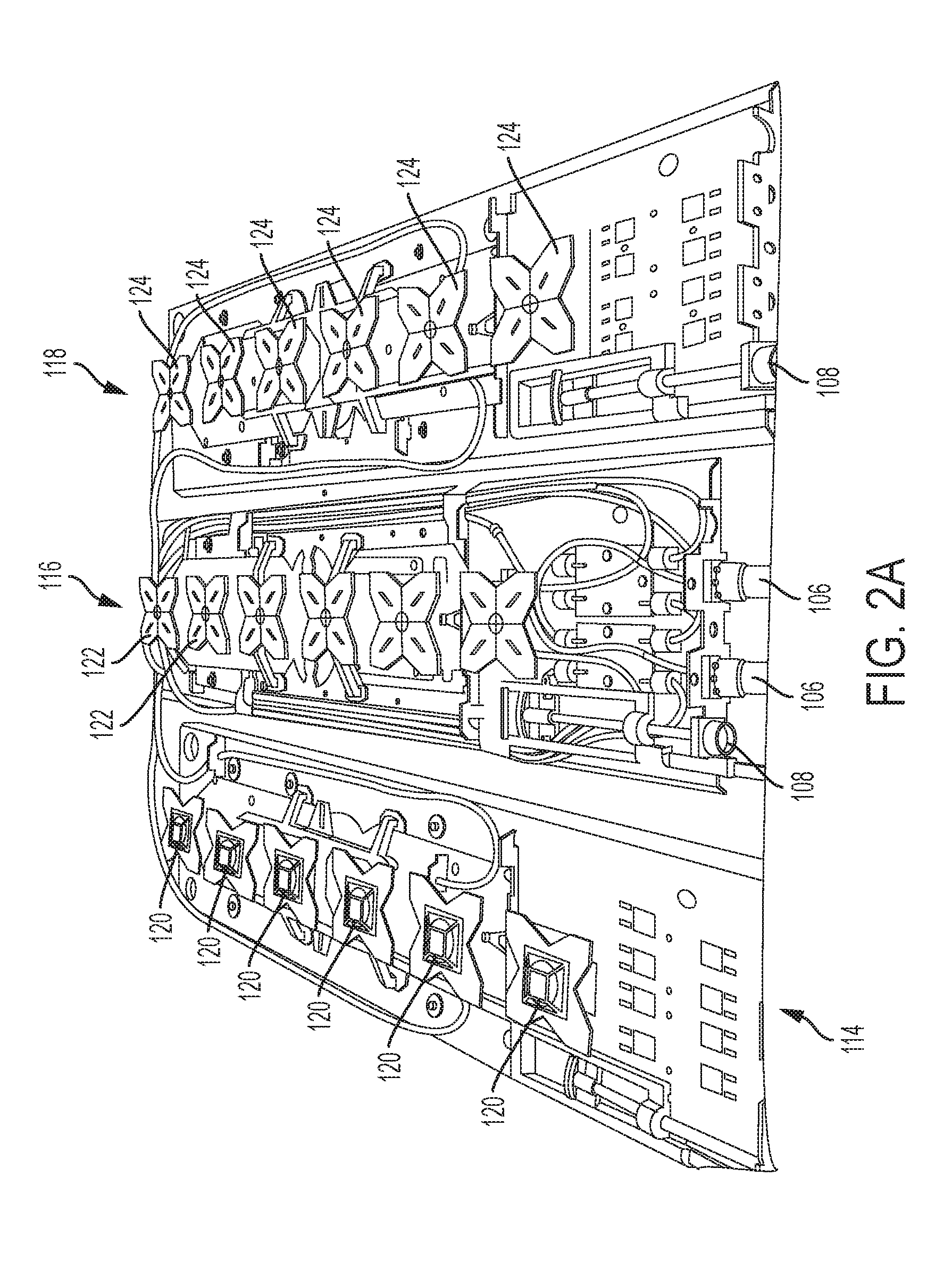
[0010]FIG. 2A is a perspective view of an interior of antenna columns of the wrap-around antenna, according to an aspect of the present disclosure;

[0011]FIG. 2B is a schematic of the antenna columns of the wrap-around antenna according to an aspect of the present disclosure;

[0012]FIG. 3A is an example of an end view of the underside of the wrap-around antenna, acco...


PUM


Abstract

Aspects of the present disclosure may be directed to a wrap-around antenna capable of being wrapped around a support structure to provide antenna patterns for a communication system. Such an assembly may be aesthetically pleasing and, because the antenna assembly allows for radiation away from the support structure, scattering effects due to interference from the support structure may be eliminated.

Description

CROSS-REFERENCE TO RELATED APPLICATIONS[0001]This application claims the benefit of U.S. Provisional Patent Application No. 62 / 173,304, filed on Jun. 9, 2015, the entire contents of which are incorporated herein by reference in their entirety.BACKGROUND[0002]Wireless operators are using more spectrum bands and increasingly more spectrum within each band to accommodate increased subscriber traffic, and for the deployment of new radio access technologies. Macro cell base station antennas serving large areas have been used in an effort to meet these traffic demands. These macro cell base station antennas may typically be deployed on a dedicated tower or building top.[0003]A newer trend involves adding small-cell base station antennas (“small-cell antennas”), which may be particularly useful in urban areas. Small-cell antennas are often installed on pre-existing objects of a city infrastructure. For example, a small-cell antenna may be housed within a cylindrical radome that is either m...

Claims


Application Information

Patent Timeline
IPC IPC(8): H01Q1/24H01Q21/20H01Q1/12
CPCH01Q1/246H01Q21/205H01Q1/1228H01Q1/42H01Q3/06H01Q3/32H01Q21/0006H01Q5/42
Inventor MALEY, GREGORY J.VEIHL, JONATHON C.BUONDELMONTE, CHARLES J.BRADLEY, EDWARD
Owner COMMSCOPE TECH LLC
Why Eureka
Try Eureka