Component mounting system and component mounting method in component mounting system

a component mounting system and component technology, applied in the direction of electrical components, electrical apparatus, etc., can solve the problems of generating a shift in the component supply position of the tape feeder, nozzles may not be able to accurately suck components, and mounting faults, etc., to shorten the model changing time

Active Publication Date: 2016-12-15
PANASONIC INTELLECTUAL PROPERTY MANAGEMENT CO LTD
View PDF3 Cites 4 Cited by
  • Summary
  • Abstract
  • Description
  • Claims
  • Application Information

AI Technical Summary

Benefits of technology

[0011]Accordingly, it is possible to shorten the model changing time, and it is possible to correctly determine whether or not to use the supply position shifting data.

Problems solved by technology

In the component mounter, there is a case in which shifting is generated in the component supply position of the tape feeder, caused by a manufacturing error, an assembly error, or the like of the tape feeder.
When the component supply position is shifted, the suction nozzle may not be able to accurately suck the component and a mounting fault may occur.
However, the creation of the supply position shifting data as an item of set-up changing work requires a fixed amount of time, since it is necessary to image the component supply position of each individual tape feeder.

Method used


Image

  • Component mounting system and component mounting method in component mounting system
  • Component mounting system and component mounting method in component mounting system
  • Component mounting system and component mounting method in component mounting system

Examples


Embodiment Construction

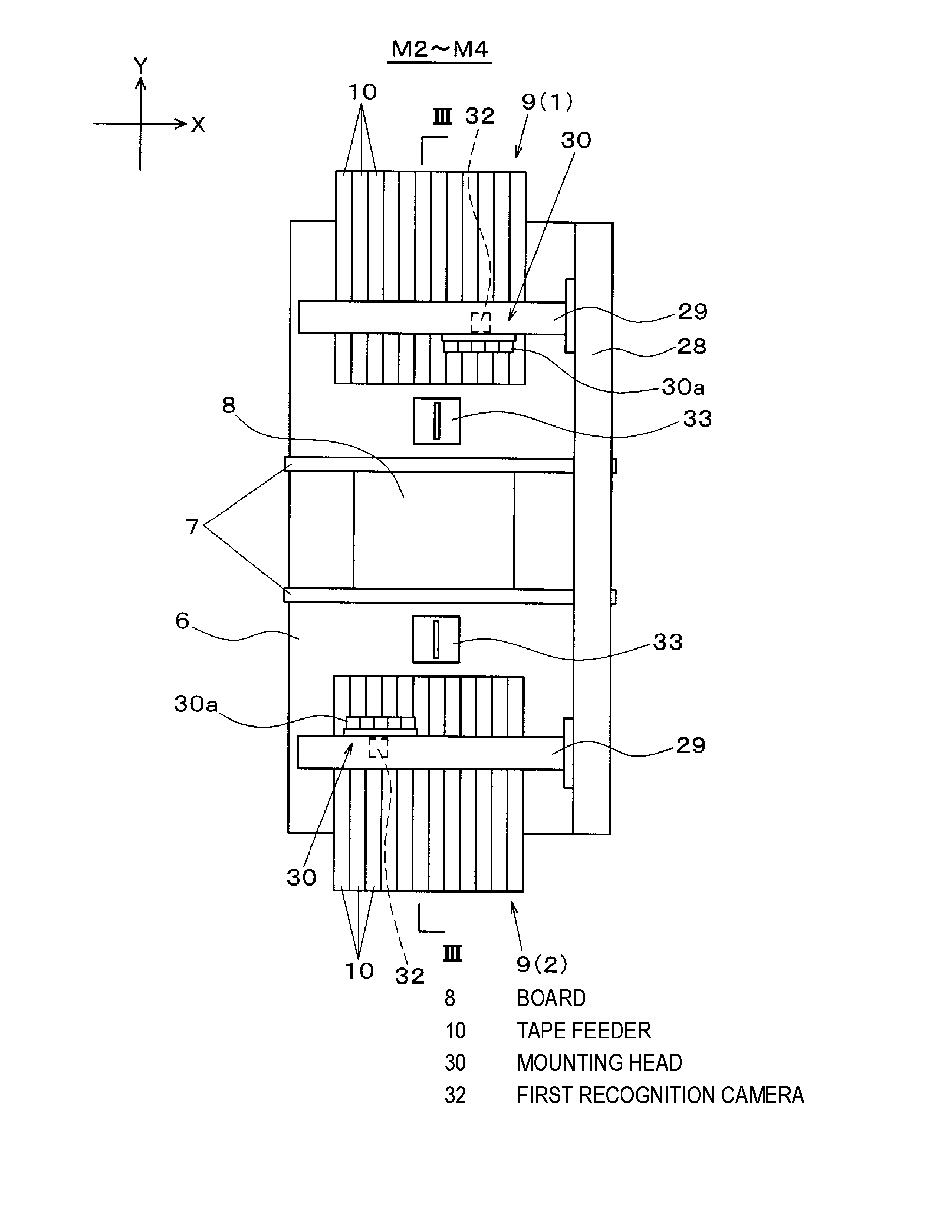
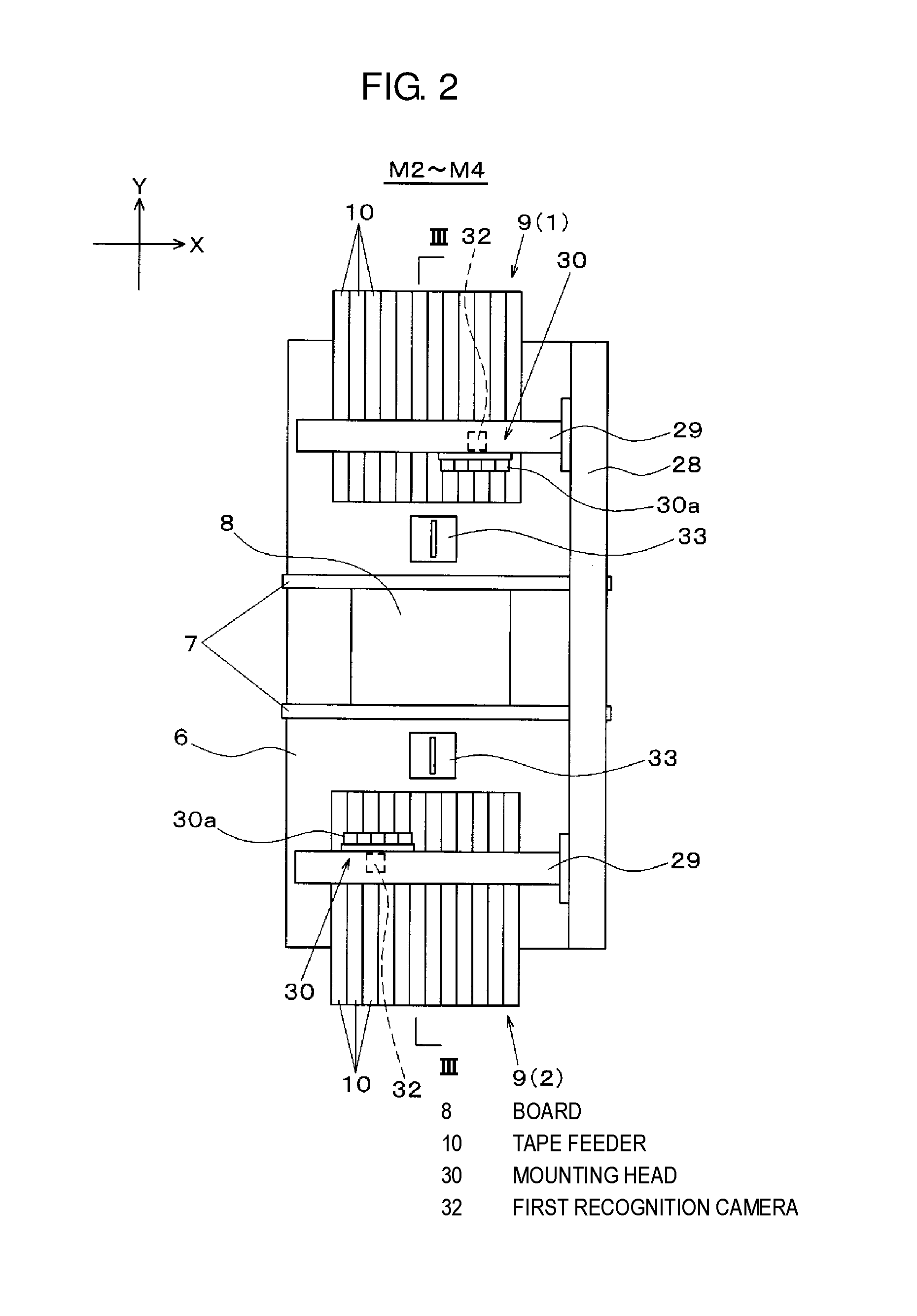
[0027]Before describing the embodiment of the present invention, a concise description will be given of the problems in the device of the related art. In the related art including JP-A-8-181488, the following problem can occur since the supply position shifting data, which is created by the device external to the component mounter of the set-up changing target, is applied, as it is, to the teaching of the suction position. It is not possible to attach the carriage to the component mounter while the component mounter of the set-up changing target is operating in order to produce a different model. For example, during this period, there is a case in which the tape feeder for which the supply position shifting data has already been created is removed from the carriage for some reason, and a different tape feeder is attached instead. In this case, since the teaching of the suction position in relation to the different tape feeder is performed based on the supply position shifting data o...


PUM

PropertyMeasurementUnit
timeaaaaaaaaaa
suction positionaaaaaaaaaa
structureaaaaaaaaaa

Abstract

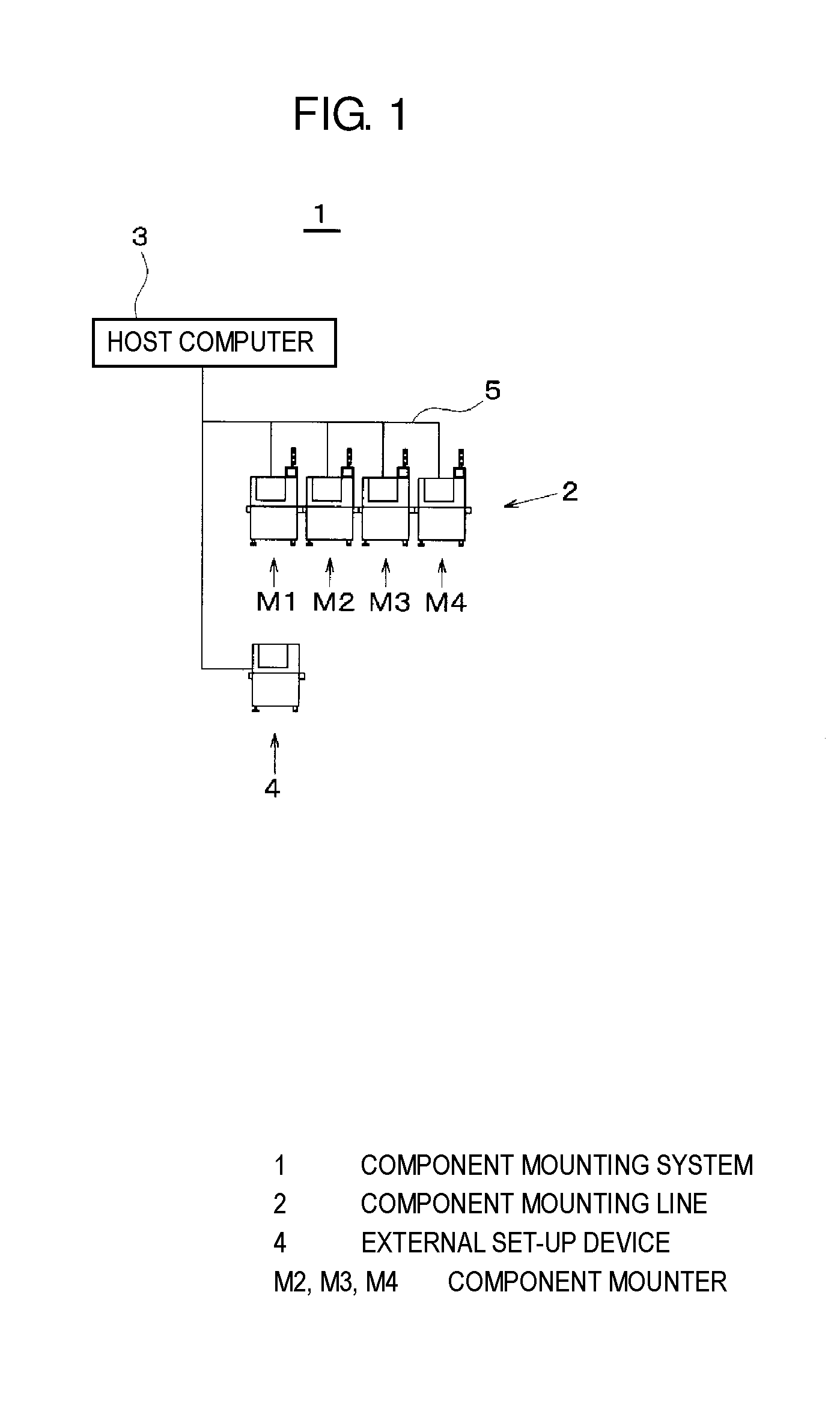
An external set-up device calculates a shift amount of a supply position of a component which is supplied by a tape feeder that is disposed on the carriage. The storage stores supply position shifting data in which the shift amount of the component supply position is related to a feeder address and a feeder ID. The component mounter compares the feeder ID of the tape feeder with the feeder ID included in the component supply position shifting data which is read from the storage, and, in a case in which the feeder IDs do not match, calculates the shift amount of the component supply position of the corresponding tape feeder and updates the supply position shifting data. The component mounter mounts the components onto a board based on the updated component supply position shifting data.

Description

BACKGROUND OF THE INVENTION[0001]1. Field of the Invention[0002]The present invention relates to a component mounting system including a component mounting line which is formed by linking a plurality of component mounters which mount components on a board, and relates to a component mounting method in the component mounting system.[0003]2. Description of the Related Art[0004]In a component mounter which mounts a component held by a suction nozzle that is attached to the mounting head onto a board, a tape feeder is widely used as a part feeder which continually supplies components to the mounting head. A plurality of the tape feeders are disposed on a carriage which can be freely attached to and detached from the component mounter. The tape feeder supplies a component to a predetermined component supply position by intermittently feeding a carrier tape, the suction nozzle picks up the component which is supplied to the component supply position and mounts the component onto the board...

Claims


Application Information

Patent Timeline
Patent Type & Authority Applications(United States)
IPC IPC(8): H05K13/04H05K13/08
CPCH05K13/08H05K13/0408H05K13/04H05K13/0417H05K13/0857H05K13/0812Y10T29/49131
Inventor SUMI, HIDEKI
Owner PANASONIC INTELLECTUAL PROPERTY MANAGEMENT CO LTD
Why Eureka
Try Eureka