Steel wire transmission system for three-dimensional printer and adjusting mechanism thereof

Active Publication Date: 2016-12-22
TECO IMAGE SYST
View PDF11 Cites 7 Cited by
  • Summary
  • Abstract
  • Description
  • Claims
  • Application Information

AI Technical Summary

Benefits of technology

[0007]An object of the present invention provides a steel wire transmission system for a three-dimensional printer and an adjusting mechanism of the steel wire transmission system. Since the adjusted tension of a steel wire is used to move a slide block, the steel wire transmission system of the present invention has the benefits of the conventional screw transmission system (e.g.,

Problems solved by technology

Therefore, it is an important issue to increase the precision and speed of the FDM technology.
Once the tooth structure of the transmission belt 10 is engaged with and disengaged from the tooth structure of the driving pulley 11 or the driven pulley 12, the friction between the corresponding tooth structures and the assembling tolerance of the corresponding tooth structures may result in a backlash problem.
Under this circumstance, the positioning precision is deteriorated.
That is, even

Method used


Image

  • Steel wire transmission system for three-dimensional printer and adjusting mechanism thereof
  • Steel wire transmission system for three-dimensional printer and adjusting mechanism thereof
  • Steel wire transmission system for three-dimensional printer and adjusting mechanism thereof

Examples


Embodiment Construction

[0023]The present invention will now be described more specifically with reference to the following embodiments. It is to be noted that the following descriptions of preferred embodiments of this invention are presented herein for purpose of illustration and description only. It is not intended to be exhaustive or to be limited to the precise form disclosed.

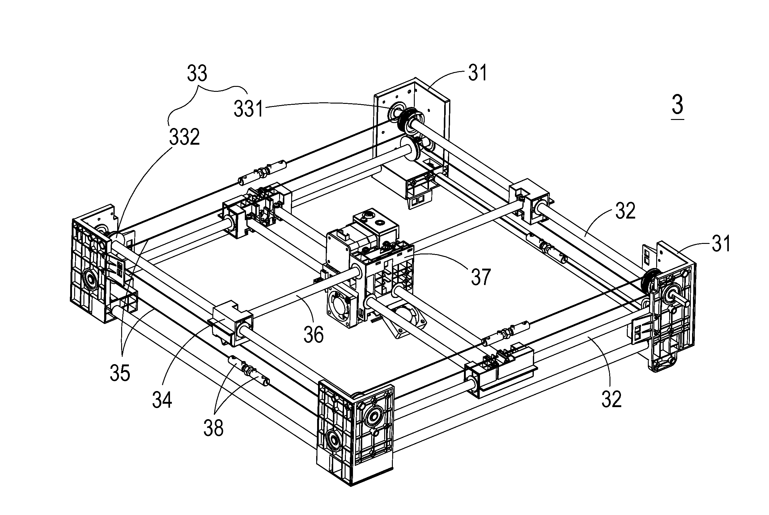
[0024]FIG. 3 schematically illustrates a steel wire transmission system for a three-dimensional printer according to an embodiment of the present invention. As shown in FIG. 3, the steel wire transmission system 3 comprises plural slide rail seats 31, plural slide rails 32, plural wheel sets 33, plural slide blocks 34, plural steel wires 35, plural guide rods 36 and a printhead module 37. The plural slide rails 32 are disposed on the corresponding slide rail seats 31 in order to implement the multi-axis transmission. Each wheel set 33 comprises a driving wheel 331 and a driven wheel 332 corresponding to the driving wheel 331. Eac...


PUM

PropertyMeasurementUnit
Timeaaaaaaaaaa

Abstract

A steel wire transmission system includes plural slide rail seats, plural slide rails, plural wheel sets corresponding to the plural slide rails, plural slide blocks, plural steel wires, plural guide rods and a printhead module. The plural slide rails are disposed on the corresponding slide rail seats. Each wheel set includes a driving wheel and a driven wheel corresponding to the driving wheel. The driving wheel and the driven wheel of each wheel set are fixed at two ends of the corresponding slide rail. Each slide block is sheathed around the corresponding slide rail and movable between the corresponding driving wheel and the corresponding driven wheel. The plural steel wires are wound around the corresponding wheel sets. Each guide rod is connected with two corresponding slide blocks. The printhead module is connected with the plural guide rods.

Description

FIELD OF THE INVENTION[0001]The present invention relates to a transmission system for a three-dimensional printer, and more particularly to a steel wire transmission system for a three-dimensional printer and an adjusting mechanism of the steel wire transmission system.BACKGROUND OF THE INVENTION[0002]In recent years, three-dimensional printing technologies, also referred as additive manufacturing (AM) technologies are rapidly developed and become increasingly popular. As known, there are various AM technologies. In accordance with the operating principle of the AM technology, a three-axis transmission system or a single-axis transmission system and nozzles cooperate to extrude a plastic material or other build material in order to produce a three-dimensional object. The overall quality of the three-dimensional object is dependent on nozzle control and size precision. The size precision is influenced by the transmission precision of the three-axis transmission system or the single-...

Claims


Application Information

Patent Timeline
IPC IPC(8): B29C67/00F16G11/04F16H19/06F16G11/12
CPCB29C67/0085F16G11/12F16G11/046B33Y30/00F16H19/06F16H2019/0686F16H19/0672F16G9/00F16G11/00F16G11/08B29C64/236F16H35/18
Inventor CHANG, YU-JENCHOU, KEN-TECHEN, TING-CHUNCHEN, CHIEN-YING
Owner TECO IMAGE SYST
Why Eureka
Try Eureka