

Tape cartridge and tape printing device
a technology of tape printing and tape cartridge, which is applied in the direction of printing, inking apparatus, printing mechanisms, etc., can solve the problems of difficult to pull out, tape cartridges tend to be caught somewhere, and cannot be smoothly carried out, so as to achieve the effect of reducing the size of the device and ensuring smooth loading or unloading
- Summary
- Abstract
- Description
- Claims
- Application Information
AI Technical Summary
Benefits of technology
Problems solved by technology
Method used
Image

Examples
first embodiment
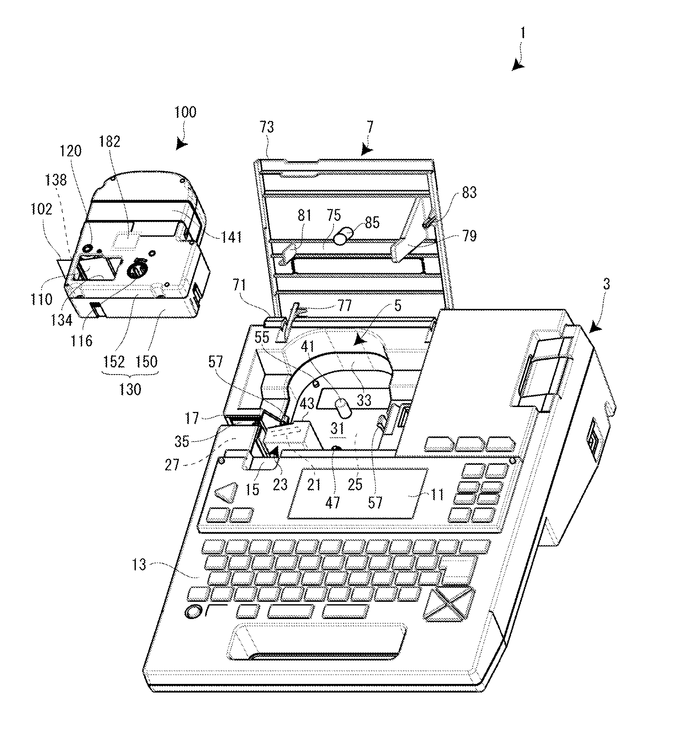
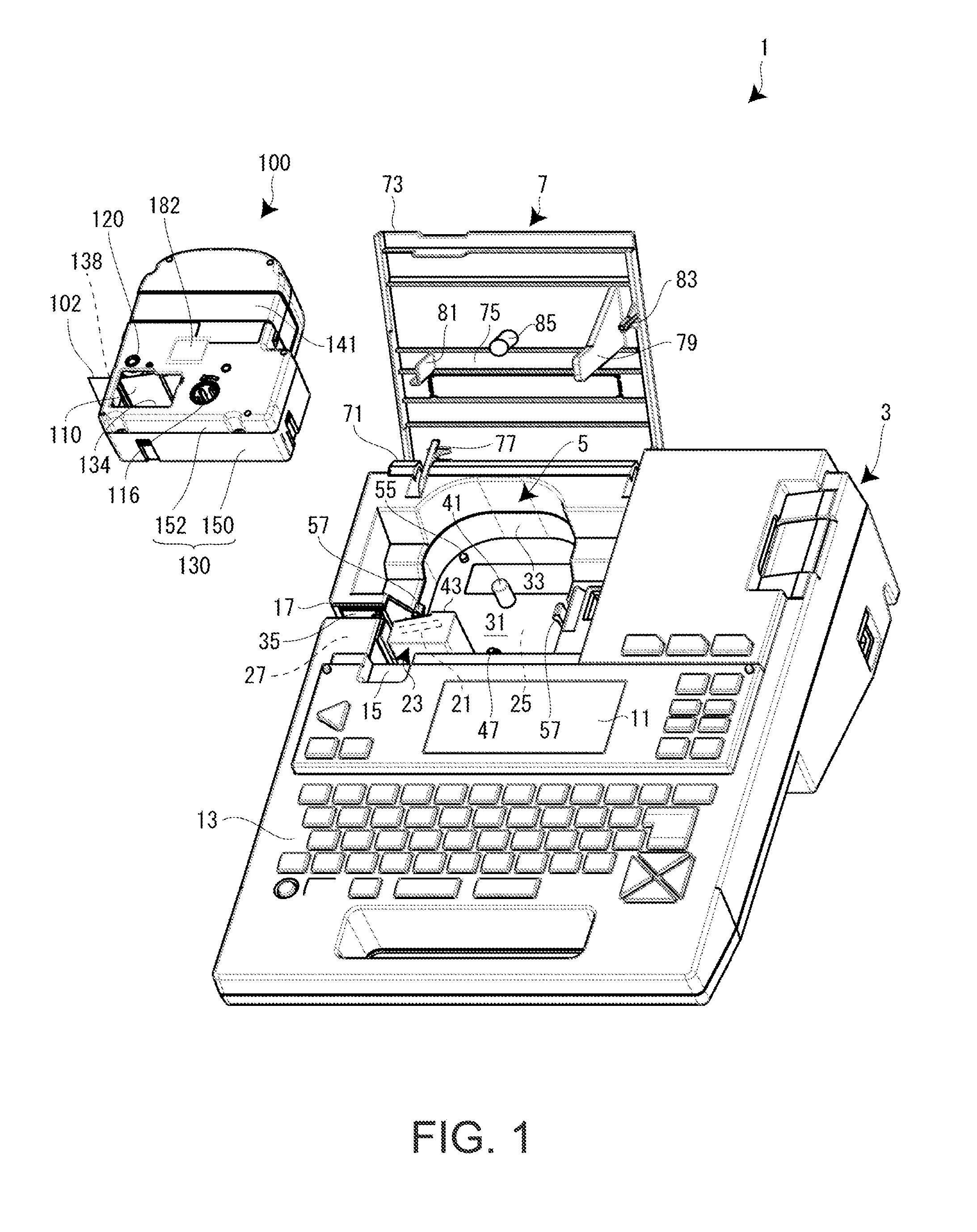
[0080]Next, referring to FIG. 7 and FIGS. 8A, 8B and 8C, the structure of the tab portion 182 of the tape cartridge 100 according to a first embodiment will be described in detail along with the structure of the pressing portion 85 of the open / close cover 7. As described above, the tab portion 182 is provided on the front side of the upper case 152, and the pressing portion 85 is provided in such a way as to protrude on the back side of the open / close cover 7, corresponding to the tab portion 182.
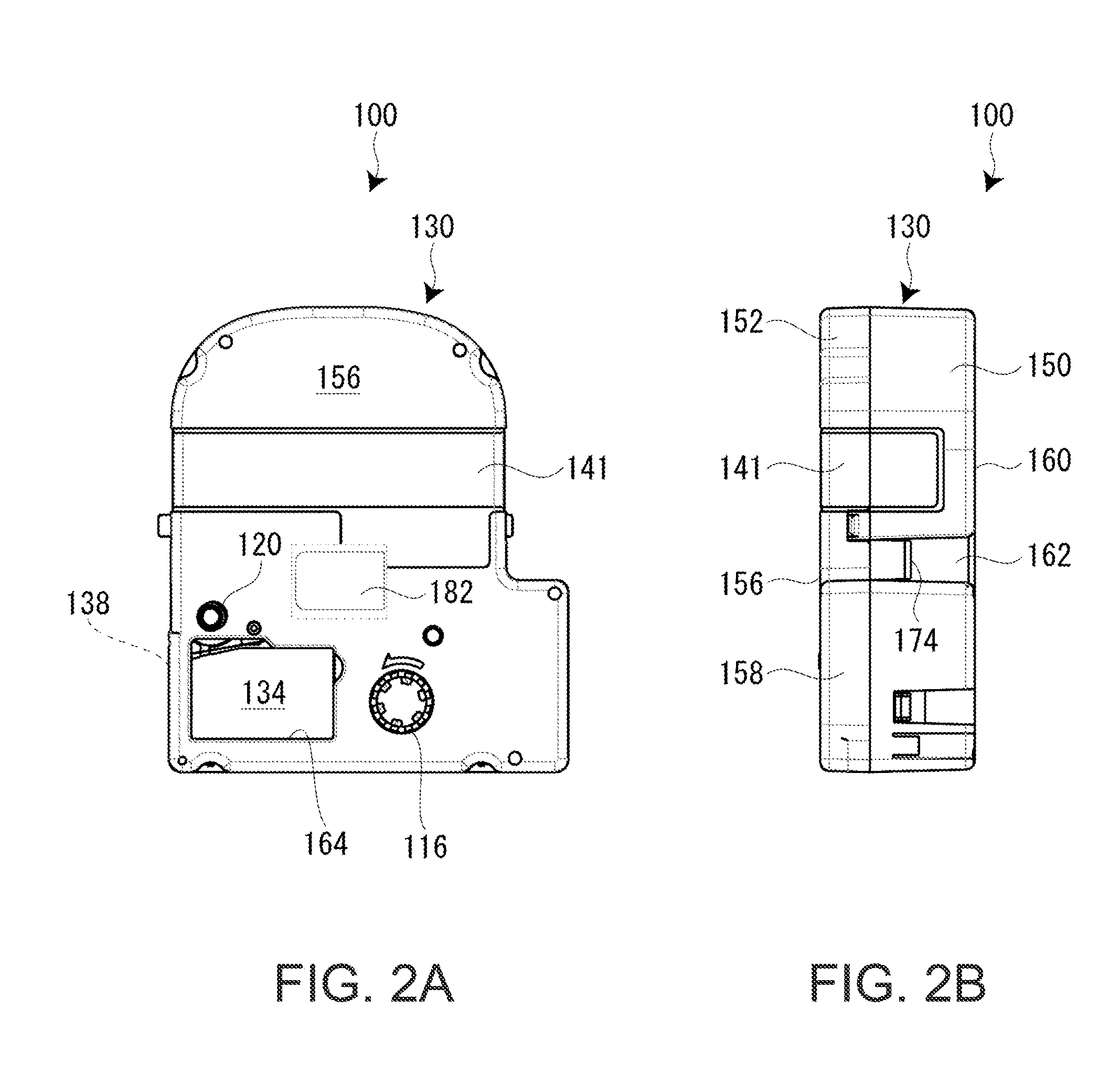
[0081]As shown in FIG. 7 and FIGS. 8A-8C, on the tape cartridge 100, the tab portion 182 is provided at a substantially middle position on an imaginary line L connecting the pair of left and right hook receiving portions 174. As described above, the pair of hook pieces 57 provided upright on the loading base 31 of the cartridge loading section 5 is hooked on the pair of hook receiving portions 174. Thus, the tape cartridge 100 is prevented from floating up, and at the same time, the hooked ...
second embodiment
[0093]Next, referring to FIG. 9 and FIGS. 10A-10C, the structure of a tab portion 182A of a tape cartridge 100A according to a second embodiment will be described in detail along with the structure of the pressing portion 85 of the open / close cover 7. Also, in the second embodiment, different parts from those in the first embodiment will be mainly described.
[0094]As shown in FIG. 9 and FIGS. 10A-10C, the tab portion 182A in the second embodiment, too, is arranged at or near a position where the pull-out resistance due to the unloading of the tape cartridge 100A is balanced, that is, at a substantially middle position on an imaginary line L connecting the pair of hook receiving portions 174, as in the first embodiment. In this case, too, the recessed portion 260 is provided at the middle position on the top wall portion 156 (case wall) of the upper case 152, and the tab portion 182A is arranged in such a way as to be accommodated in the recessed portion 260.
[0095]The recessed portion...
third embodiment
[0104]Next, referring to FIG. 11, the structure of a tab portion 182B of a tape cartridge 100B according to a third embodiment will be described. Also, in the third embodiment, different parts from those in the first and second embodiments will be mainly described.
[0105]As shown in FIG. 11, the tab portion 182B in the third embodiment, too, is arranged at or near a position where the pull-out resistance due to the unloading of the tape cartridge 100B is balanced, that is, at a substantially middle position on an imaginary line L connecting the pair of hook receiving portions 174 (see FIG. 7), as in the first embodiment. However, in this case, the tab portion 182B is fixed to the recessed portion 260, in the state of being accommodated in the recessed portion 260.
[0106]The tab portion 182B includes a tab portion main body 350 in the shape of a circular plate, and a support and fixing portion 352 which supports the tab portion main body 350 and fixes the tab portion main body 350 to t...
PUM
 Abstract
Description
Claims
Application Information