Vibrating discharging device

A technology of unloading device and material box, which is applied in the direction of transportation, packaging, loading/unloading, etc. It can solve the problems of reduced service life of the unloading hopper, heavy load of the unloading hopper, complex structure of the unloading hopper, etc., and achieves simple structure and convenient operation Effect

Inactive Publication Date: 2017-02-15
WUXI TEHENG TECH CO LTD
View PDF9 Cites 5 Cited by
  • Summary
  • Abstract
  • Description
  • Claims
  • Application Information

AI Technical Summary

Problems solved by technology

However, this method makes the structure of the unloading hopper more complicated, and the load of the unloading hopper is heavier, resulting in a reduction in the service life of the unloading hopper

Method used


Image

  • Vibrating discharging device
  • Vibrating discharging device
  • Vibrating discharging device

Examples


Embodiment Construction

[0013] The present invention will be further described below in conjunction with specific drawings.

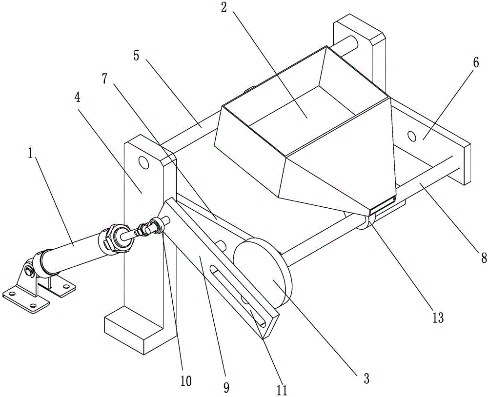
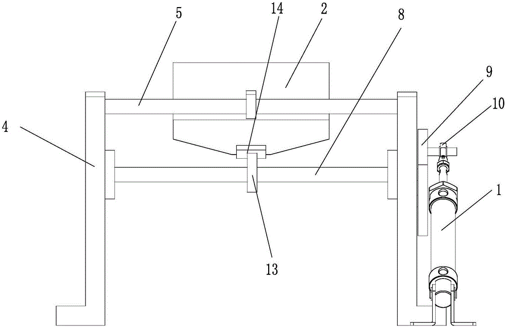
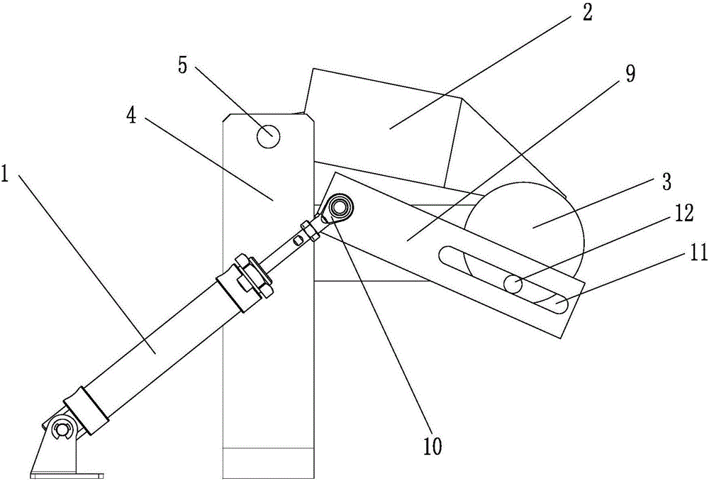
[0014] Such as Figure 1 ~ Figure 3 As shown: the vibrating unloading device includes a cylinder 1, a material box 2, a rotating wheel 3, a frame 4, a mounting rod 5, a first mounting plate 6, a second mounting plate 7, a rotating wheel mounting shaft 8, and a rotating plate 9 , Joint bearing 10, chute 11, eccentric shaft 12, support cam 13, card slot 14, etc.

[0015] Such as Figure 1 ~ Figure 3 As shown, the vibrating unloading device of the present invention includes a frame 4, on which a mounting rod 5 is set, and the mounting rod 5 is rotated to install the material box 2; Mounting plate 6 and the second mounting plate 7, one end of the first mounting plate 6 and the second mounting plate 7 is installed on the frame 4, and the rotating wheel is installed between the first mounting plate 6 and the other end of the second mounting plate 7 Installation shaft 8, rotating ...


PUM


Abstract

The invention relates to a vibrating discharging device. The device comprises a rack and is characterized in that a mounting rod is arranged on the rack; a material box is rotationally mounted on the mounting rod; a first mounting plate and a second mounting plate are arranged on two sides of the rack; one end of the first mounting plate and one end of the second mounting plate are mounted on the rack; a rotating wheel mounting shaft is rotationally mounted between the other end of the first mounting plate and the other end of the second mounting plate; a rotating wheel is mounted on the rotating wheel mounting shaft; an eccentric shaft is arranged on the outer end surface of the rotating wheel; a rotating plate is rotationally arranged on the second mounting plate; one end of the rotating plate is rotationally connected with an extending rod of a gas cylinder; a sliding groove is formed in the other end of the rotating plate in the length direction of the rotating plate; the eccentric shaft on the outer end surface of the rotating wheel is arranged in the sliding groove; and a supporting cam is arranged on the rotating wheel mounting shaft and supports the front end of the material box. The device is simple in structure and convenient to operate, and smooth and continuous discharging of viscous materials can be guaranteed.

Description

technical field [0001] The invention relates to a vibrating unloading device, in particular to an unloading device used in material or conveying industrial equipment, and belongs to the technical field of conveying and unloading equipment. Background technique [0002] In the prior art, unloading devices are often used in logistics or transport industrial equipment. The current unloading device generally adopts the unloading hopper, and discharges the material by turning over the unloading hopper. However, for materials with cohesiveness, the simple method of turning over the discharge hopper cannot completely unload the material, and manual assistance is also required, which makes the operation more troublesome. [0003] In order to solve the unloading problem of such cohesive materials, in the prior art, a vibrating motor is generally installed on the unloading hopper to vibrate the unloading hopper to help unloading. However, this method makes the structure of the unloa...

Claims


Application Information

Patent Timeline
IPC IPC(8): B65G65/44
CPCB65G65/44
Inventor 罗怀锋
Owner WUXI TEHENG TECH CO LTD
Why Eureka
Try Eureka