
Computational Pipeline and Architecture for Multi-View Displays

a multi-view display and computational pipeline technology, applied in the field of electronic displays, can solve the problems of high bit rate to handle, and achieve the effect of reducing complexity

Active Publication Date: 2016-12-22
MISAPPLIED SCI INC
View PDF3 Cites 29 Cited by
  • Summary
  • Abstract
  • Description
  • Claims
  • Application Information

AI Technical Summary

Benefits of technology

This patent describes a technology for creating displays that can show different images to different viewers simultaneously. These displays have multiple pixels that emit light in a wide range of directions, making it possible for multiple viewers to watch the display from different angles and see the same image. The technology also takes advantage of redundancies in the visual content to reduce the complexity of distributing data to the pixels. In some cases, the technology achieves a 50% reduction in data volume compared to a previous technique. Overall, this technology simplifies the process of creating multi-view displays and reduces the amount of data needed to distribute them.

Problems solved by technology

Even with modern electronics and telecommunication capabilities, these are high bit rates to handle.

Method used


Image

  • Computational Pipeline and Architecture for Multi-View Displays
  • Computational Pipeline and Architecture for Multi-View Displays
  • Computational Pipeline and Architecture for Multi-View Displays

Examples


Embodiment Construction

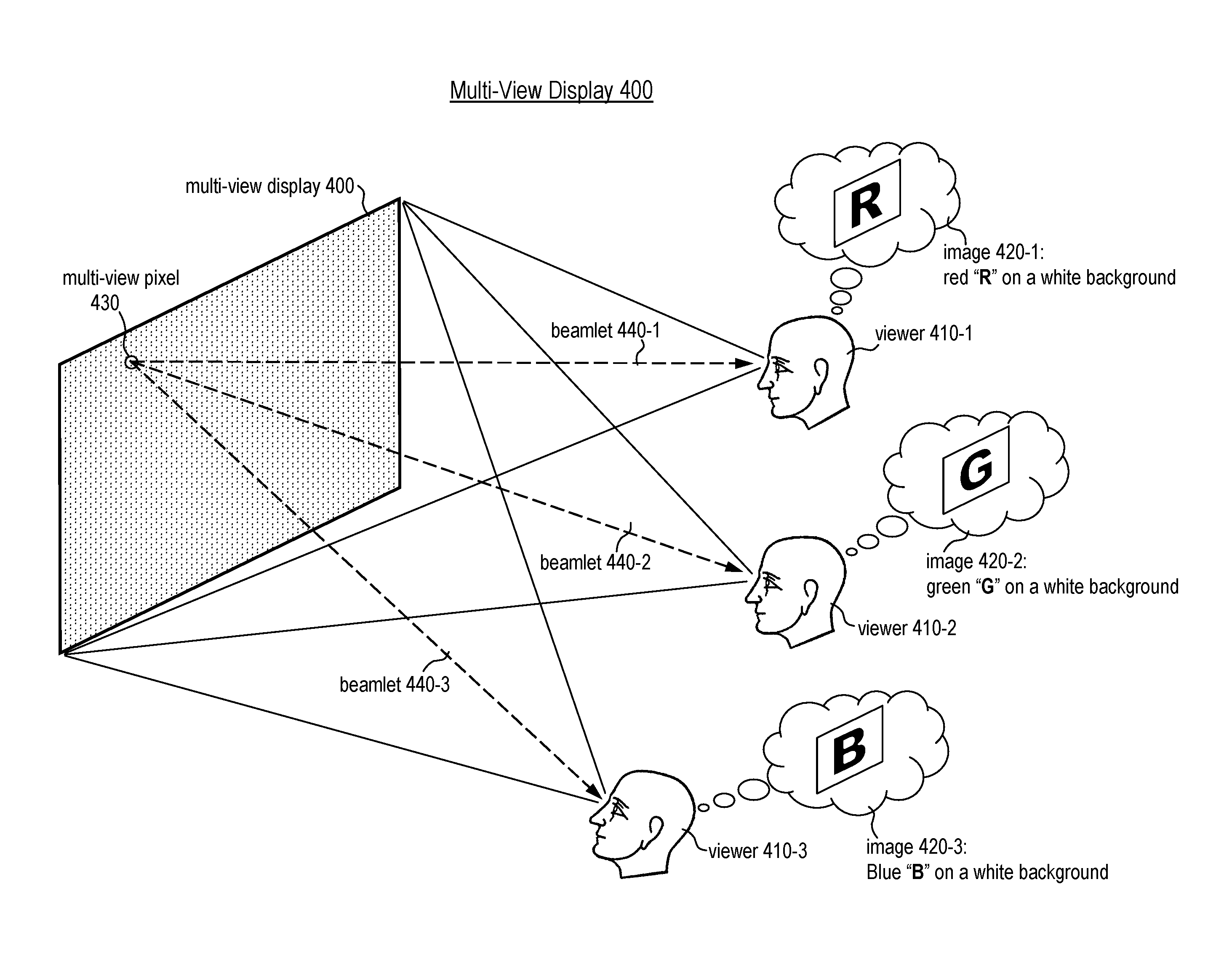
[0051]FIG. 4 illustrates the functionality of a multi-view display. In the figure, multi-view display 400 is viewed simultaneously by three viewers 410-1, 410-2, and 410-3. The three viewers are positioned at three distinct positions from which the multi-view display is visible. Each of the three viewers sees a different image on the display surface of the multi-view display. The three different images seen by the three viewers are depicted in the figure as images 420-1, 420-2, and 420-3. In particular, viewer 410-1 sees a red letter “R” on a white background, viewer 410-2 sees a green letter “G” on a white background, and viewer 410-3 sees a blue letter “B” on a white background.

[0052]For each of the three viewers, the experience of viewing the display is similar to viewing a conventional display, such as a standard television set, but each viewer sees a different image on the display surface of the multi-view display. Each viewer is, possibly, not even aware that other viewers are...


PUM


Abstract

A multi view display is a display capable of simultaneously showing different images to viewers that see the display from different locations. Viewers do not see the images intended for other viewers at other locations. A multi view display forms images via a collection of multi-view pixels. A multi-view pixel is able to emit different light in different directions; in each direction, parameters of emitted light such as brightness, color, etc., can be controlled independently of the light emitted in other directions. Embodiments of the present invention comprise a computational pipeline and architecture for efficiently distributing image data to the multi-view pixels of a multi-view display.

Description

CROSS REFERENCE TO RELATED APPLICATIONS[0001]The underlying concepts, but not necessarily the language, of the following case are incorporated by reference:[0002](1) U.S. provisional application No. 62 / 180,300.If there are any contradictions or inconsistencies in language between this application and one or more of the cases that have been incorporated by reference that might affect the interpretation of the claims in this case, the claims in this case should be interpreted to be consistent with the language in this case.[0003]This case claims benefit of the following provisional application:[0004](1) U.S. provisional application No. 62 / 180,300.FIELD OF THE INVENTION[0005]The present invention relates to electronic displays, and, more particularly, to electronic displays intended for simultaneously displaying multiple distinct images.BACKGROUND[0006]Ever since antiquity, people have created pictures. In ancient times, pictures were exclusively static pictures generated, for example,...

Claims


Application Information

Patent Timeline
Patent Type & Authority Applications(United States)
IPC IPC(8): G06T11/60G06T7/40G09G3/00
CPCG06T11/60G09G3/006G09G2320/028G09G2330/12G09G2340/10G06T7/408G09G3/003H04N13/324H04N2013/403H04N13/327H04N13/307H04N13/398H04N13/351G09G5/00G09G2320/0693G09G2350/00G09G2320/0261G09F19/14G06T7/90
Inventor NG, ALBERT HANDIETZ, PAUL HENRYTHOMPSON, DAVID STEVEN
Owner MISAPPLIED SCI INC
Learn More