
Active Intrinsically Safe Circuit

a technology of intrinsically safe circuits and active circuits, applied in emergency protective circuit arrangements, emergency protection arrangements for limiting excess voltage/current, etc., can solve problems such as excess current, energy waste, and circuits that do not create or allow operation above safe limits

Inactive Publication Date: 2016-12-22
LOWERS WILLIAM +1
View PDF2 Cites 5 Cited by
  • Summary
  • Abstract
  • Description
  • Claims
  • Application Information

AI Technical Summary

Benefits of technology

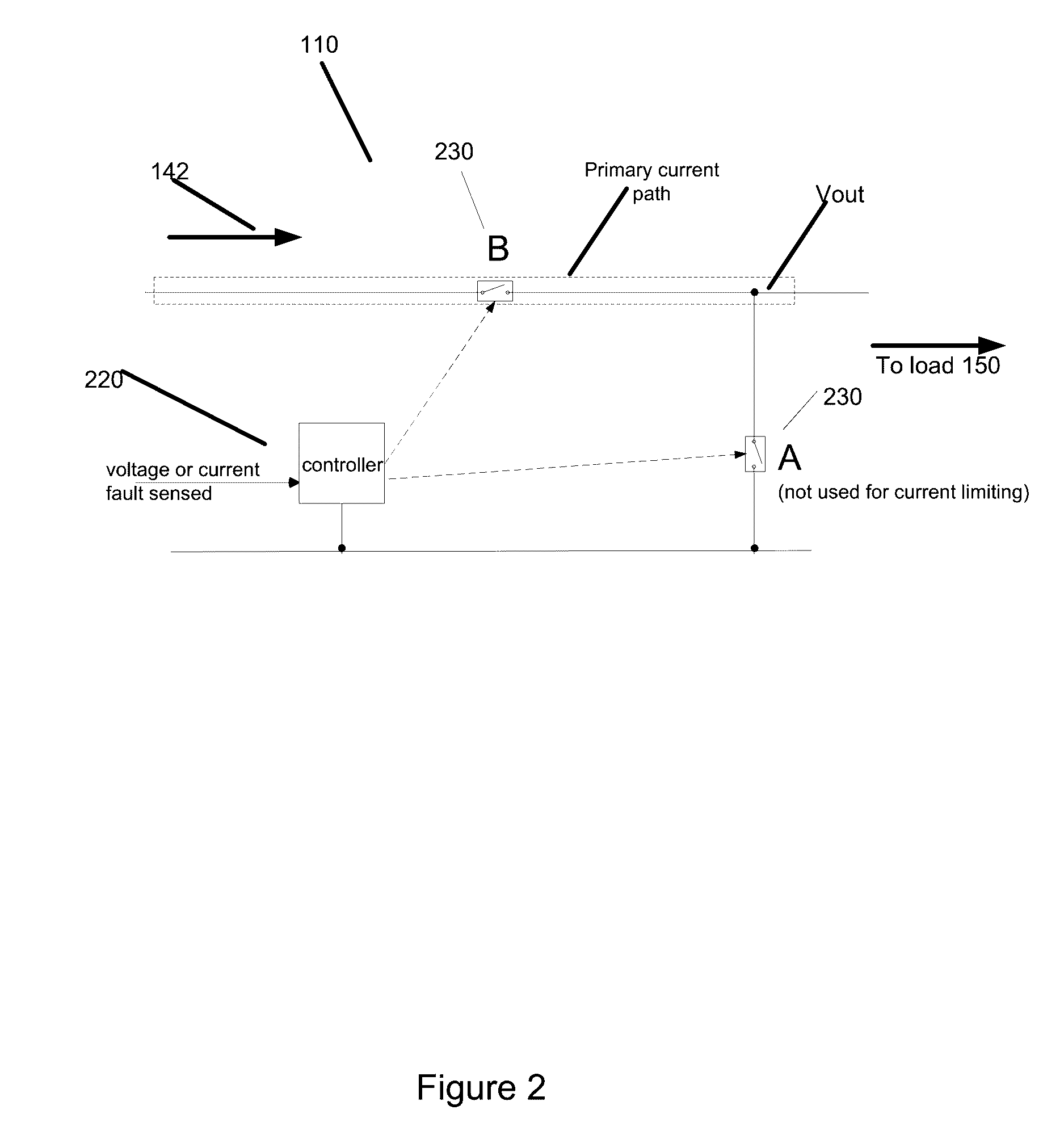
The patent describes an active intrinsically safe circuit that can detect and prevent electrical faults. It does this by using a switch that acts as a temporary electrical crowbar to divert current from the load and prevent damage. The circuit can also use existing alternative circuit paths to test voltage or current, temporarily deny power to the load, and recover when the current or voltage comes back into compliance. The circuit is controlled by active analog devices, discrete digital logic, or digital processors, and may be organized in sets of two or more in various topologies.

Problems solved by technology

Care must be taken so that electrical circuits do not create or allow operation above safe limits for voltage, current, power, or heat that would otherwise be sufficient to ignite gasses, other chemicals, or particles in hazardous areas.
The other electrical device then generates heat while it further consumes energy from the power source and generally causes a fuse to open the circuit.
Also, high direct current drawn by a load may be caused by a capacitor or perhaps a transistor shorting to ground, causing excess current.
A circuit that continues to draw current that is not delivered to the primary load means that the energy is wasted.
Recharging cycles reduce the life of batteries.
Furthermore, if the circuit path is not configured properly with a fuse or other means to shut off current flow, catastrophic results may take place with particular battery technologies such as Lithium-Ion.
Still further, maintaining and accessing battery-powered equipment in the field may be impractical for logistical, geographical, or other reasons.

Method used


Image

  • Active Intrinsically Safe Circuit
  • Active Intrinsically Safe Circuit
  • Active Intrinsically Safe Circuit

Examples


Embodiment Construction

[0033]In these descriptions, we may generally refer to voltage, current, or power generically as electrical energy or energy. However, specific applications of active current, active voltage, or active power limitation are contemplated in the embodiments.

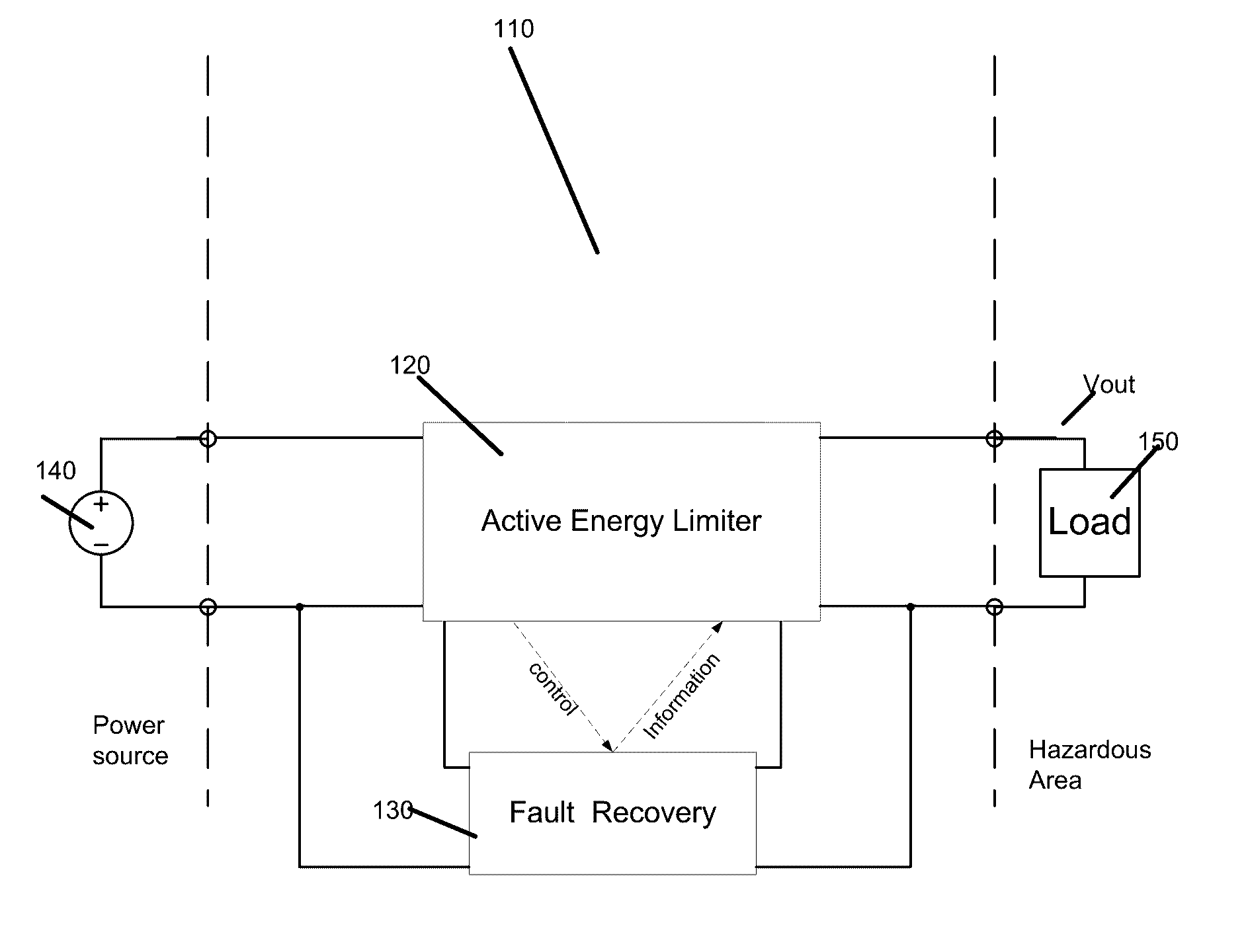
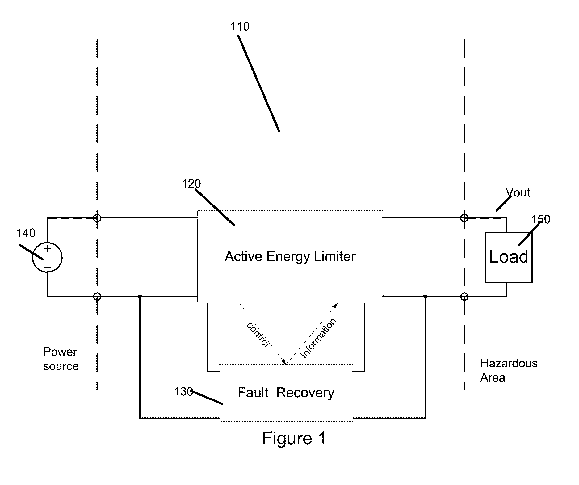
[0034]FIG. 1 shows the general concept of an intrinsically safe circuit 110 placed between an electrical energy source and a load 150, where the intrinsically safe circuit 110 is in a hazardous area. An electrical energy source 140 may entail direct or alternating current. A fault recovery circuit 130 is connected generally in parallel so as to be able to monitor and control voltage and current from the source. Together, the active energy limiter 120 the fault recovery circuit 130 comprise the intrinsically safe circuit 110. When a fault arises, such as an over-current or over-voltage condition, the active energy limiter 120 will cut off or otherwise limit voltage or current to the load 150. Thus, the load 150 is protected. After th...


PUM


Abstract

An active intrinsically safe circuit for detecting and mitigating non-compliance of current, voltage, power, or heat to at a load which resides in a hazardous area, where non-compliance may cause danger to life or harm to property. The intrinsically safe circuit monitors current, voltage, power, or heat, shuts off or otherwise limits current, voltage, or power. The intrinsically safe circuit then tests for return of compliance, and acts to restore current, voltage, and power to the load upon return of compliance.

Description

CROSS-REFERENCE TO RELATED APPLICATIONS[0001]The present application for patent claims the benefit of U.S. Provisional Application Ser. No. 62 / 181,549, entitled, “ACTIVE INTRINSICALLY SAFE CIRCUIT,” filed Jun. 18, 2015, and hereby expressly incorporated by reference herein.STATEMENT REGARDING FEDERALLY SPONSORED RESEARCH OR DEVELOPMENT[0002]Not ApplicableREFERENCE TO SEQUENCE LISTING, A TABLE, OR A COMPUTER PROGRAM LISTING COMPACT DISK APPENDIX[0003]Not ApplicableBACKGROUND OF THE INVENTION[0004]The subject technology is in the technical field of intrinsically safe circuits, as well as systems, methods, and apparatus making use thereof.SUMMARY OF THE INVENTION[0005]Care must be taken so that electrical circuits do not create or allow operation above safe limits for voltage, current, power, or heat that would otherwise be sufficient to ignite gasses, other chemicals, or particles in hazardous areas. Prior art in the area of intrinsically safe current limiting circuit often deploys a ...

Claims


Application Information

Patent Timeline
Patent Type & Authority Applications(United States)
IPC IPC(8): H02H9/00
CPCH02H9/008
Inventor LOWERS, WILLIAMABNETT, ALBERT
Owner LOWERS WILLIAM
Learn More