Device and method for launching a projectile across a range

a technology of a projectile and a range, which is applied in the field of devices and methods for launching projectiles over a distance, can solve the problems of unoptimized technology of throwing projectiles, and achieve the effects of convenient launching of projectiles, reduced learning curve, and greater control

Active Publication Date: 2016-12-29
SYMTAR VENTURES
View PDF4 Cites 10 Cited by
  • Summary
  • Abstract
  • Description
  • Claims
  • Application Information

AI Technical Summary

Benefits of technology

[0009]Illustrative embodiments of the disclosure are generally directed to a device and method that facilitates launching a projectile over a distance across a range. The device and method is configured to launch a projectile, such as a golf ball, across a range. The device enables a golf ball to be launched across a golf course with greater control and with a shorter learning curve than is possible with a traditional golf club. The ease of loading the golf ball into the launching device and swinging the launching device in a forward direction adds greater control and accuracy to the golf ball due to an increase in angular momentum and torque that are transmitted from the device to the golf ball.
[0010]In one embodiment, the device includes a C-shaped head defined by a nest, a pair of lateral retention arms, and a base. A distal portion is longer than a proximal portion to create spin. The lateral arms hold the ball in place. Though, the lateral arms do not necessarily have a function. The concave nest creates greater surface area for the projectile which imparts spin on the projectile. The base of the C-shaped head remains stationary while releasably attaching to a shaft. Though, in one alternative embodiment, the base of the C-shaped head pivots. The shaft is operable to swing the C-shaped head in a direction for launching the projectile.
[0011]It is significant to note that the design intent of the more distal section of the nest to the ball is the riding surface of the projectile and the creator of spin. There is clearance within the nest that, when combined with momentum, causes the projectile to only ride on the more distal section. The more proximal section of the nest is shorter for ease of installation of the projectile, mold-ability, reducing surface area / drag and to promote more friction to the more distal section. This is especially true in the case where the technique used to throw the projectile isn't optimal.

Problems solved by technology

This is especially true in the case where the technique used to throw the projectile isn't optimal.

Method used


Image

  • Device and method for launching a projectile across a range
  • Device and method for launching a projectile across a range
  • Device and method for launching a projectile across a range

Examples


Embodiment Construction

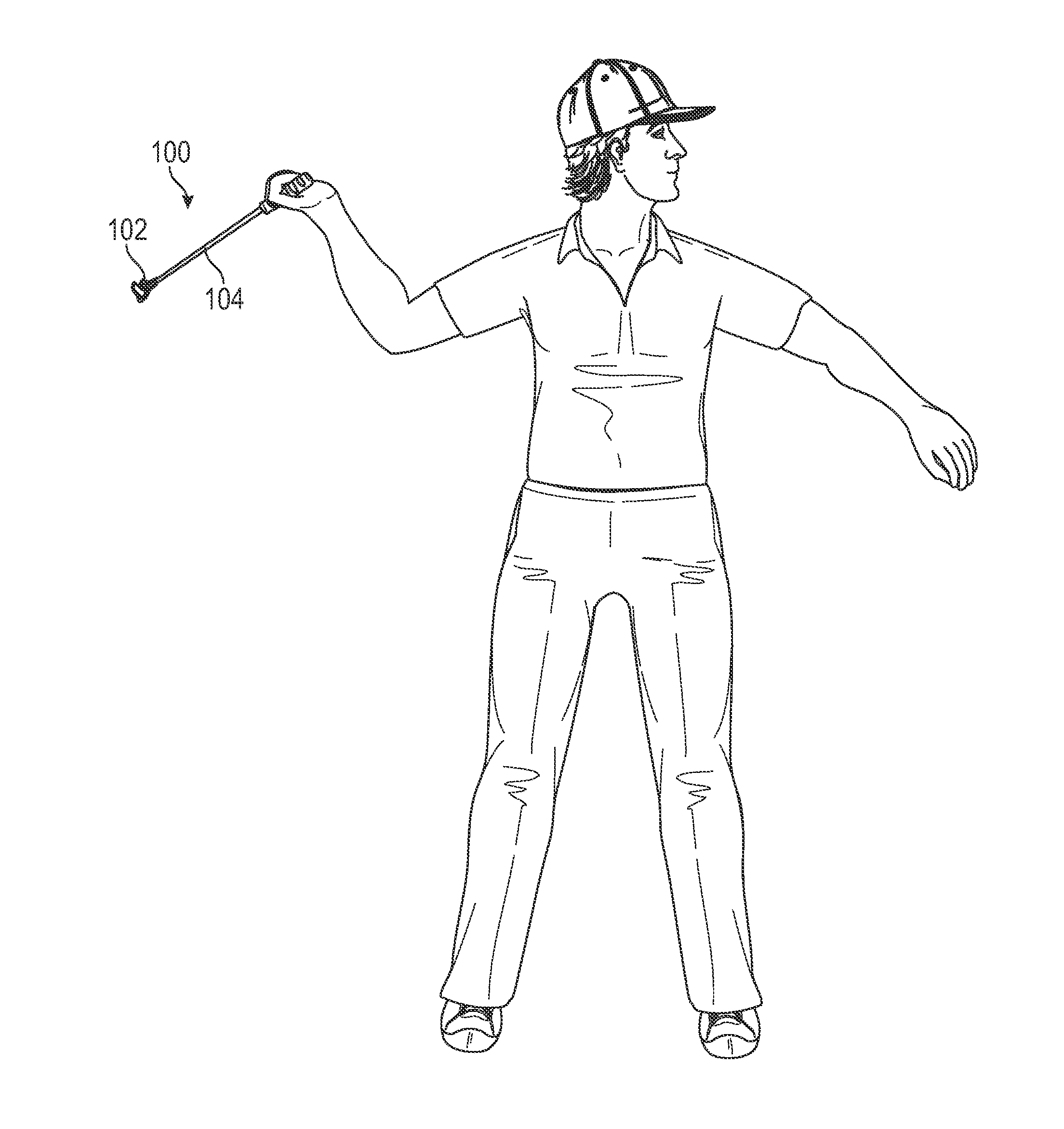
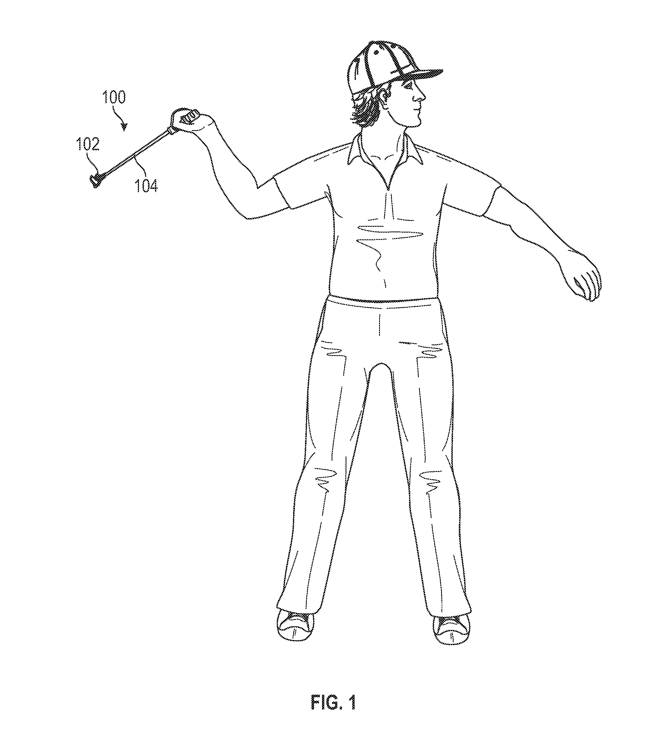
[0060]The following detailed description is merely exemplary in nature and is not intended to limit the described embodiments or the application and uses of the described embodiments. As used herein, the word “exemplary” or “illustrative” means “serving as an example, instance, or illustration.” Any implementation described herein as “exemplary” or “illustrative” is not necessarily to be construed as preferred or advantageous over other implementations. All of the implementations described below are exemplary implementations provided to enable persons skilled in the art to make or use the embodiments of the disclosure and are not intended to limit the scope of the disclosure, which is defined by the claims. For purposes of description herein, the terms “upper,”“lower,”“left,”“rear,”“right,”“front,”“vertical,”“horizontal,” and derivatives thereof shall relate to the invention as oriented in FIG. 1. Furthermore, there is no intention to be bound by any expressed or implied theory pres...


PUM


Abstract

A device and method for launching a projectile, such as a golf ball, across a range. The device enables a golf ball to be launched across a golf course with greater control than is possible with a traditional golf club. The ease of loading the projectile into the launching device and swinging the launching device forward adds greater distance to the projectile due to an increase in angular momentum and back spin on the projectile. The device includes a C-shaped head defined by a nest, a pair of lateral retention arms, and a base. A distal portion is longer than a proximal portion to create backspin on the projectile. The concavity and lateral arms hold the projectile in place. The distal and proximal portions terminate at concave points that grip dimples on the projectile. The base is fixedly attached to a shaft, which is used for swinging the head.

Description

CROSS REFERENCE OF RELATED APPLICATIONS[0001]This application claims the benefits of U.S. provisional application No. 62 / 186,200, filed Jun. 29, 2015 and entitled LAUNCHING DEVICE AND METHOD FOR FACILITATING LONG SHOTS OF A GOLF BALL ACROSS A GOLF COURSE, which provisional application is incorporated by reference herein in its entirety.FIELD OF THE INVENTION[0002]The present invention relates generally to a device and method for launching a projectile over a distance. More so, the present invention relates to a device and method that facilitates launching a projectile, such as a golf ball, accurately and over a distance across a range by retaining the projectile in a generally C-shaped head comprising of a concave nest having asymmetrical lengths that engage a projectile, and impart angular velocity and torque on the projectile when the device is swung in a forward direction with a shaft, such that the consequential spin on the projectile is consistent.BACKGROUND OF THE INVENTION[00...

Claims


Application Information

Patent Timeline
Patent Type & Authority Applications(United States)
IPC IPC(8): A63B67/02A63B65/12
CPCA63B65/122A63B67/02A63B2209/08A63B2209/10A63B2210/50A63B60/0081
Inventor FRYER, JOHN CORNELIUSZALER, CHRISTOPHER PAUL
Owner SYMTAR VENTURES
Why Eureka
Try Eureka