Customizable apparatus and method for transporting and depositing fluids

a technology of fluid transport and fluid depositing, which is applied in the direction of liquid/solution decomposition chemical coating, superimposed coating process, rotary lithographic machines, etc., can solve the problems of unfavorable fluid distribution, unfavorable fluid transport and depositing, and limited fluid channel size that may be incorporated into the devi

Active Publication Date: 2016-12-29
THE PROCTER & GAMBLE COMPANY
View PDF6 Cites 53 Cited by
  • Summary
  • Abstract
  • Description
  • Claims
  • Application Information

AI Technical Summary

Benefits of technology

[0006]A method for delivering a High Internal Phase Emulsion to a substrate. The method includes providing a rotating roll, The rotating roll has a central longitudinal axis, wherein the rotating roll rotates about the central longitudinal axis, an exterior surface defining an interior region and substantially surrounding the central longitudinal axis, and a vascular network configured for transporting the one or more fluids in a predetermined path from the interior region to the exterior surface of the rotating roll. The method further includes providing a High Internal Phase Emulsion to the rotating roll vascular network. The method further includes contacting a substrate with the rotating roll and contacting the substrate with the High Internal Phase Emulsion.
[0007]A method for delivering a High Internal Phase Emulsion to a substrate. The method includes providing a rotating roll, The rotating roll has a central lon

Problems solved by technology

Manufacturers may use moving rolls having primarily axial fluid flow and/or primarily circumferential fluid flow which results in uneven fluid distribution and lack of fluid reaching parts of the rolls.
In addition, such designs limit the number and sizes of fluid channels that may be incorporated into the device and limit the location of the fluid orifices stemming from those channels in a way that undermines precision.
Alternatively manufacturers use printing plates and flat surfaces, which result in slower processing or imprecision when running at high rates as the printing plate may not be able to keep up with the m

Method used


Image

  • Customizable apparatus and method for transporting and depositing fluids
  • Customizable apparatus and method for transporting and depositing fluids
  • Customizable apparatus and method for transporting and depositing fluids

Examples


Embodiment Construction

Definitions

[0054]As used herein, the “aspect ratio” of a shape is the ratio of the length of the longest dimension or diameter of the shape, in any direction, that intersects the shape's midpoint and length of the shortest dimension or diameter of the shape, in any direction, that intersects the shape's midpoint.

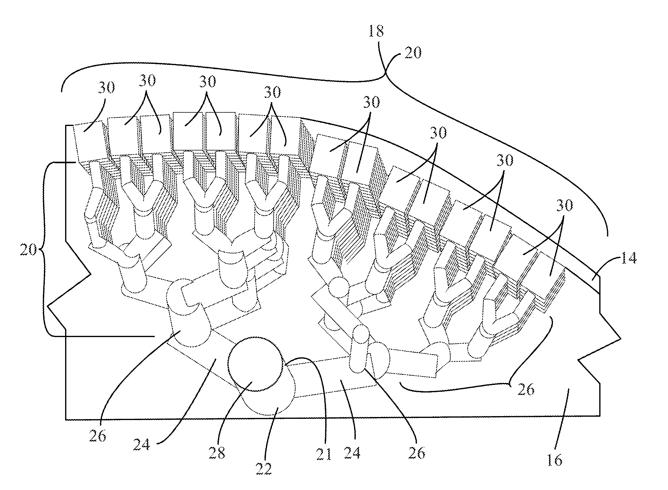
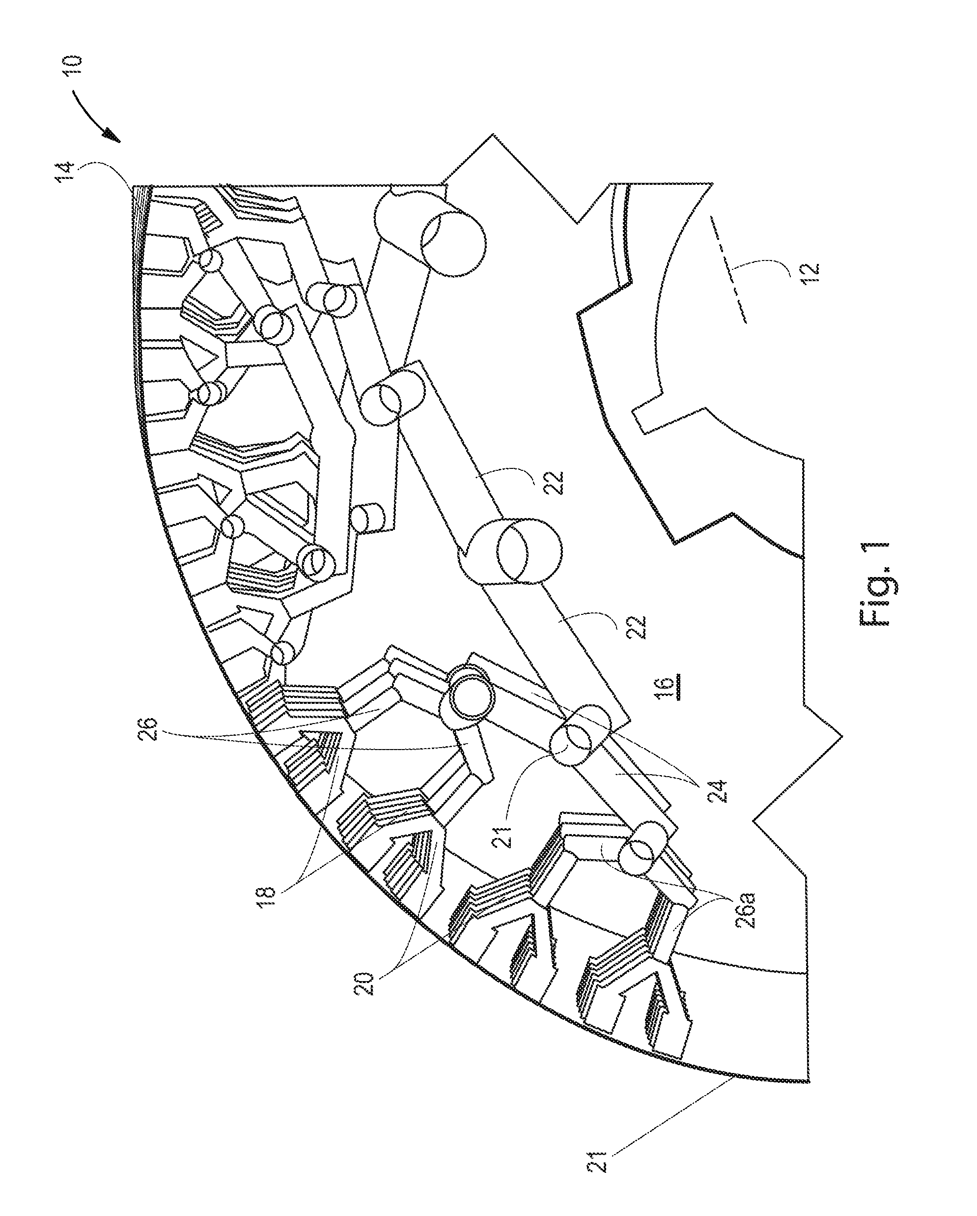
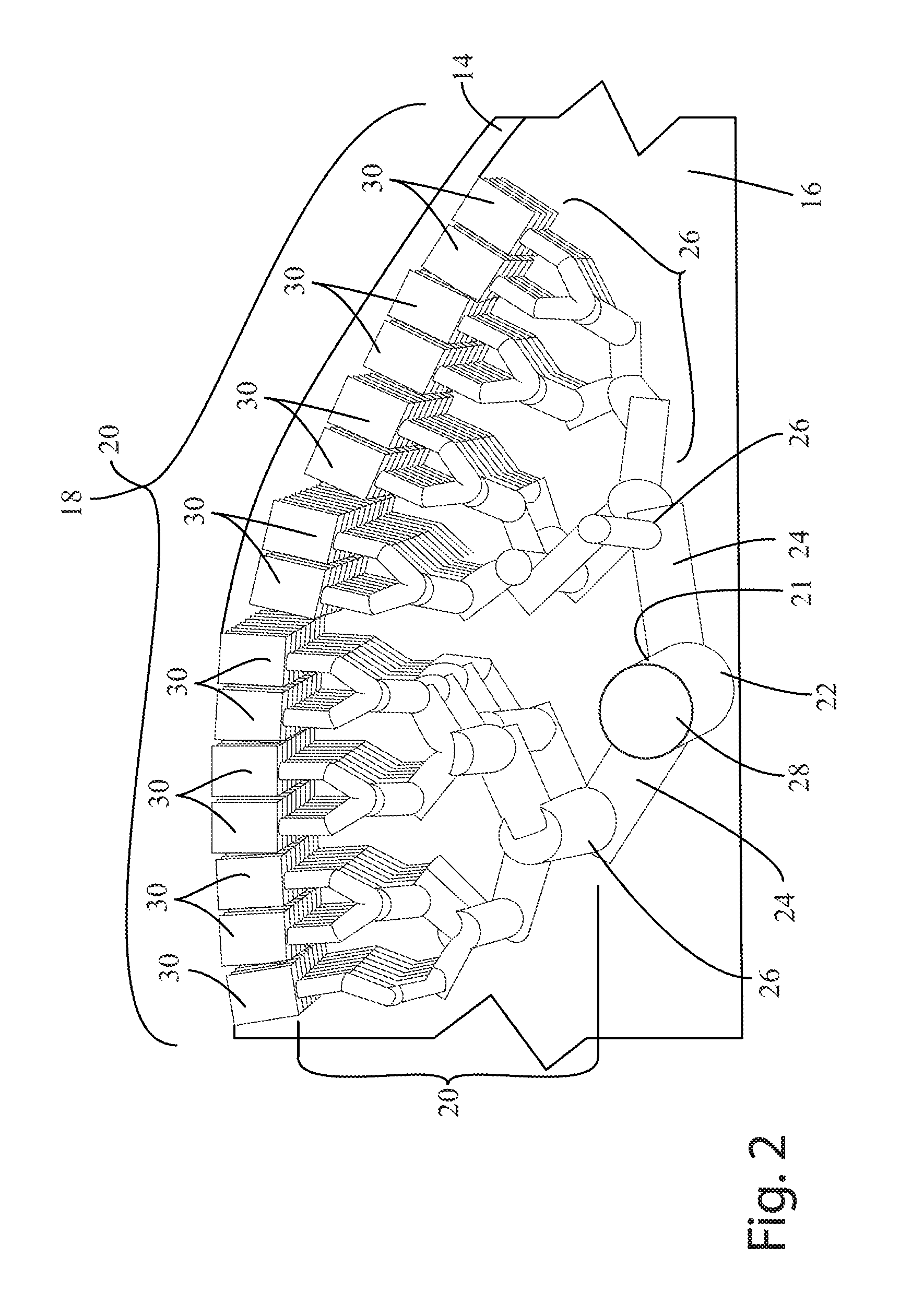
[0055]“Vascular network” as used herein means a network of channels that carry fluid from an entry, such as an inlet, to one or more exits. The channels include one or more main arteries, one or more capillaries, and / or one or more sub-capillaries. In the vascular network, each channel may be in fluid communication with another channel. In general, the entry may be at or near the main artery, and the main artery may be in direct fluid communication (i.e., without intermediate channels) with a capillary. Likewise, a capillary may be in direct fluid communication with a main artery, another capillary, and / or a sub-capillary, and / or a fluid exit (all of which are discussed more...


PUM

PropertyMeasurementUnit
Temperatureaaaaaaaaaa
Lengthaaaaaaaaaa

Abstract

A method for delivering a High Internal Phase Emulsion to a substrate. The method includes providing a rotating roll, The rotating roll has a central longitudinal axis, wherein the rotating roll rotates about the central longitudinal axis, an exterior surface defining an interior region and substantially surrounding the central longitudinal axis, and a vascular network configured for transporting the one or more fluids in a predetermined path from the interior region to the exterior surface of the rotating roll. The method further includes providing a High Internal Phase Emulsion to the rotating roll vascular network. The method further includes contacting a substrate with the rotating roll and contacting the substrate with the High Internal Phase Emulsion.

Description

FIELD OF THE INVENTION[0001]The present invention relates to equipment and methods for depositing a fluid or a plurality of fluids onto a substrate. More particularly, the invention relates to equipment and methods for dosing fluids on moving substrates.BACKGROUND OF THE INVENTION[0002]Manufacturers of consumer goods often apply absorbents in solid forms to their products. To date, manufacturers have mostly relied on the use of drums and vacuum to deliver solid absorbents to the product. To date, absorbent precursors in a fluid state are not handled in a manner that allows for precise delivery to a substrate in a controlled manner accounting for shear while having precise fluid flow control. Manufacturers may use moving rolls having primarily axial fluid flow and / or primarily circumferential fluid flow which results in uneven fluid distribution and lack of fluid reaching parts of the rolls. In addition, such designs limit the number and sizes of fluid channels that may be incorporat...

Claims


Application Information

Patent Timeline
IPC IPC(8): B05C1/08B05C1/10
CPCB05C1/0808B05C1/10B05C1/0813B41F31/22B41F31/26B41F7/265B41F13/11
Inventor MCNEIL, KEVIN BENSONBYRNE, THOMAS TIMOTHYPRODOEHL, MICHAEL SCOTTMELLIN, GUSTAV ANDREHUBBARD, JR., WADE MONROEGROSSE, PAUL AARONLENGERICH, GREGORY ALAN
Owner THE PROCTER & GAMBLE COMPANY
Why Eureka
Try Eureka