Oilfield apparatus and methods of use

a technology of oilfield apparatus and oilfield, applied in drilling machines and methods, fluid removal, construction, etc., can solve the problems of compromising the original design of the christmas tree, complex and carefully designed christmas tree equipment, and avoiding deviations in the location of critical components

Inactive Publication Date: 2016-12-29
DONALD IAN +1
View PDF3 Cites 6 Cited by
  • Summary
  • Abstract
  • Description
  • Claims
  • Application Information

AI Technical Summary

Benefits of technology

The patent describes a problem in oil and gas production systems where accessing a flow system for fluid intervention can be difficult and risky. The current methods require a choke body on a Christmas tree, which is complex and may not be able to support the weight of intervention equipment. This can lead to damage to the structure and limit access to large items of process equipment. The invention provides a solution that does not require a choke body and can be used with different types of Christmas trees. The technical effect is safer and more efficient fluid intervention in oil and gas production systems.

Problems solved by technology

Full well intervention processes and applications are often technically complex, time-consuming and have a different cost profile to fluid intervention operations.
Firstly, a Christmas tree is a complex and carefully-designed piece of equipment.
This compromises the original design of the Christmas tree, as it requires the choke to be located in a sub-optimal position.
Secondly, a choke body on a Christmas tree is typically not designed to support dynamic and / or static loads imparted by intervention equipment and processes.
Mounting a metering system (or other fluid intervention equipment) on the choke body therefore exposes that part of the Christmas tree to loads in excess of those that it is designed to withstand, creating a risk of damage to the structure.
This problem may be exacerbated in deepwater applications, where even greater loads may be experienced due to thicker and / or stiffer components used in the subsea infrastructure.
In addition to the load restrictions identified above, positioning the flow intervention equipment on the choke body may limit the access available to large items of process equipment and / or access of divers or remotely operated vehicles (ROVs) to the process equipment or other parts of the tree.
Furthermore, modifying the Christmas tree so that the chokes are in non-standard positions is generally undesirable.
Another drawback of the prior art proposals is that not all Christmas trees have chokes integrated with the system; approaches which rely on Christmas tree choke body access to the flow system are not applicable to these types of tree.

Method used


Image

  • Oilfield apparatus and methods of use
  • Oilfield apparatus and methods of use
  • Oilfield apparatus and methods of use

Examples


Embodiment Construction

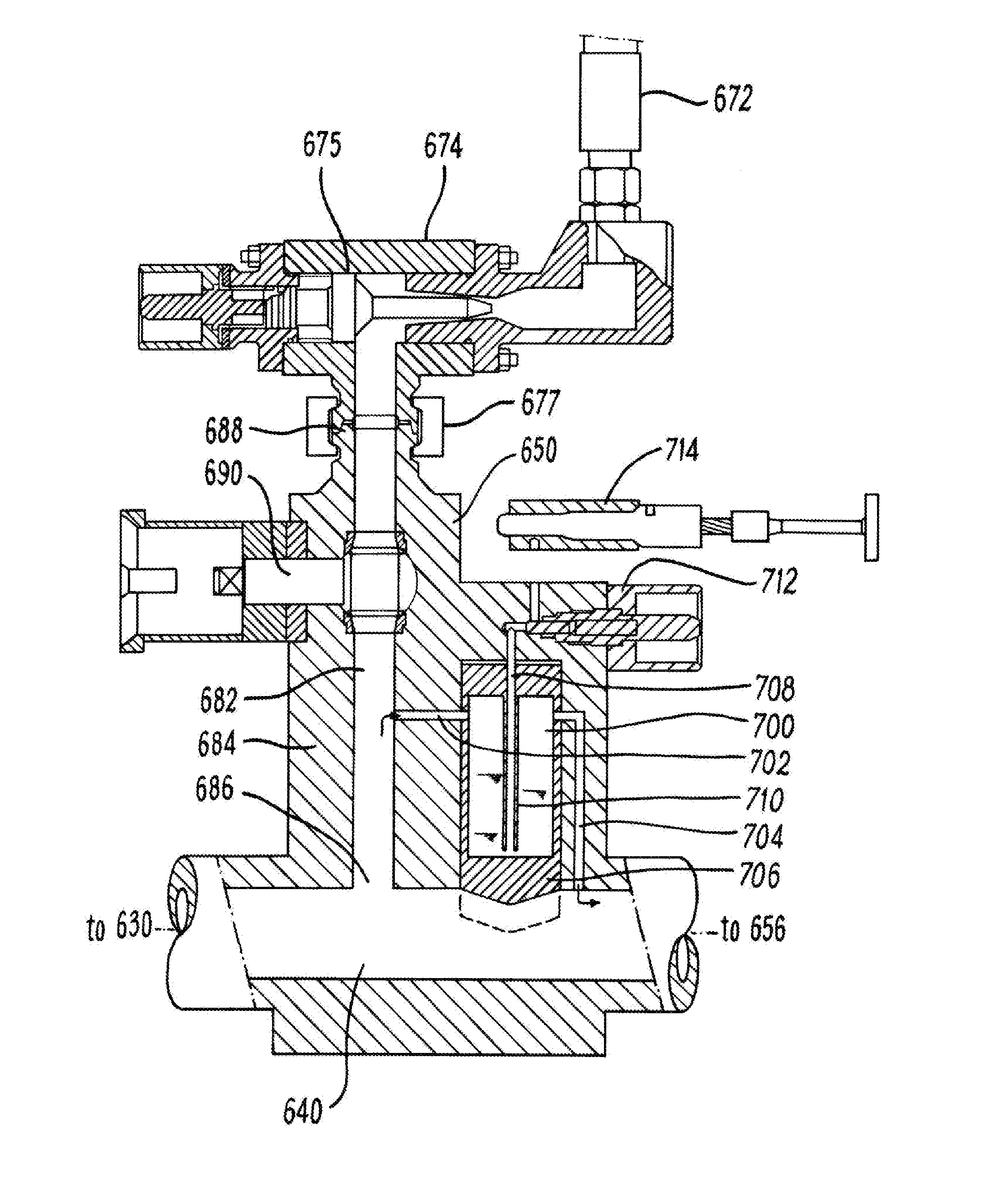
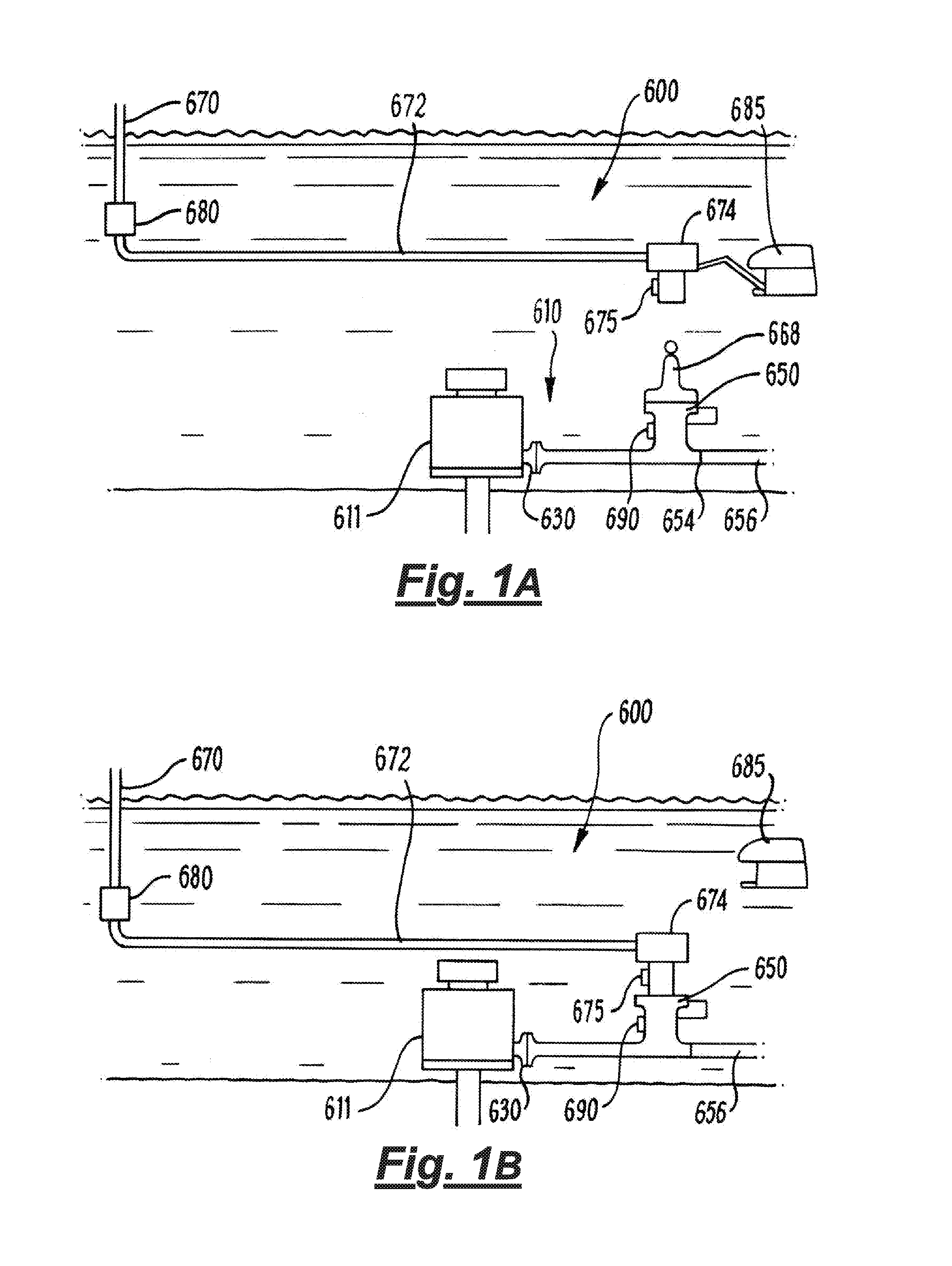
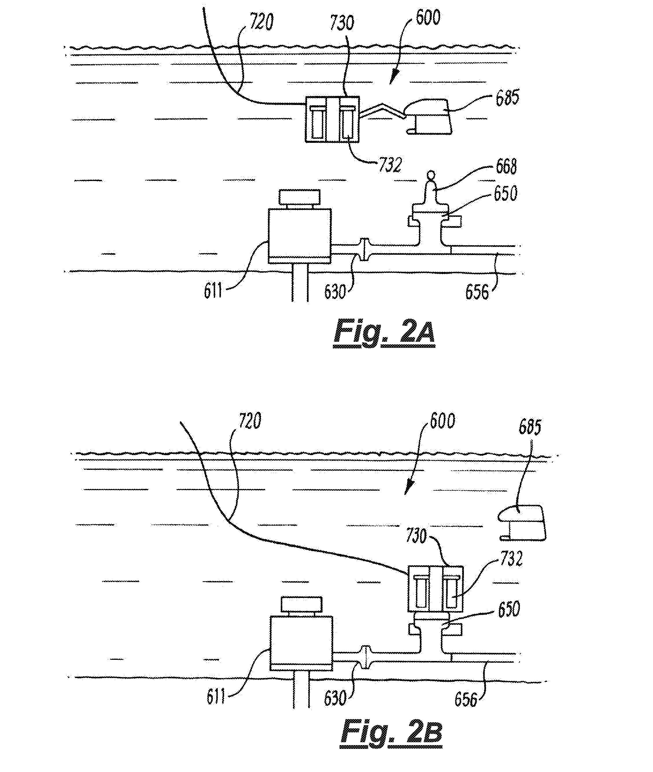
[0084]Referring firstly to FIGS. 1 to 3, a combined injection and sampling system will be described. The system, generally depicted at 600, is shown schematically in different stages of a subsea injection operation in a well squeeze application in FIGS. 1A and 1B and in a sampling mode as described below with reference to FIGS. 2A and 2B. A hub 650, configured as a combined sampling and injection hub used in the methods of FIGS. 1 and 2, is shown in more detail in FIG. 3.

[0085]The system 600 comprises a subsea flow system 610 which includes subsea manifold 611. The subsea manifold 611 is a conventional vertical dual bore Christmas tree (with internal tree components omitted for simplicity), and the system 600 utilises a hub 650 to provide access to the flow system 610. A flowline connector 630 of a production branch outlet conduit (not shown) is connected to the hub 650 which provides a single access point to the system. At its opposing end, the hub 650 comprises a standard flowline...


PUM


Abstract

The invention provides a flow control valve for a subsea hydrocarbon production system and a method of use. The flow control valve comprises an inlet configured to be in fluid communication to an injection fluid conduit and an outlet configured to be in fluid communication with a subsea flow system. A flow control mechanism is disposed in a flow path between the inlet and the outlet and is arranged to adjust a flow rate through the flow path. The flow control mechanism is configured to automatically adjust the flow rate of injection fluid through the flow path according to a pressure differential between fluid pressure at the inlet and fluid pressure at the outlet. Adjustment may be self-regulating, or may be controlled by a hydraulic control circuit.

Description

CROSS REFERENCE TO RELATED APPLICATION(S)[0001]This application is a continuation of U.S. patent application Ser. No. 14 / 396,658, filed Oct. 23, 2014, which is a U.S. National Stage Entry of International Patent Application No. PCT / GB2013 / 051058, filed Apr. 26, 2013, which claims the benefit of Provisional Patent Application No. 61 / 639,018, filed Apr. 26, 2012, the disclosures of which are hereby incorporated entirely herein by reference.BACKGROUND[0002]Technical Field[0003]The present invention relates to oilfield apparatus and methods of use, and in particular a flow control valve and method for fluid intervention in oil and gas production or injection systems. A preferred embodiment of the invention is a valve with multiple flow control functions. The invention has particular application to subsea oil and gas operations, and aspects of the invention relate specifically to methods and apparatus for fluid injection, and to combined fluid injection and sampling applications.[0004]St...

Claims


Application Information

Patent Timeline
Patent Type & Authority Applications(United States)
IPC IPC(8): E21B33/076E21B43/01E21B34/04
CPCE21B33/076E21B43/01E21B34/04E21B33/035E21B2200/06E21B43/16
Inventor DONALD, IANREID, JOHN
Owner DONALD IAN
Why Eureka
Try Eureka