Supercharge Your Innovation With Domain-Expert AI Agents!

Switch control circuit and converter including the same

a control circuit and converter technology, applied in the direction of electric variable regulation, process and machine control, instruments, etc., can solve the problems of increasing switching loss and increasing switching loss

Active Publication Date: 2016-12-29
SEMICON COMPONENTS IND LLC
View PDF3 Cites 9 Cited by
  • Summary
  • Abstract
  • Description
  • Claims
  • Application Information

AI Technical Summary

Benefits of technology

The present invention provides a switch control circuit that includes a burst mode control circuit and a converter including the switch control circuit. The burst mode control circuit generates a signal that is synchronized with the input voltage of the converter and compensates for the signal by using an edge threshold voltage in an edge area of the signal. The edge area may include a left edge area and a right edge area in each cycle of the input voltage. The burst mode control circuit may generate the signal as the same edge threshold voltage in the left edge area and the right edge area, or different edge threshold voltages in the left edge area and the right edge area. The edge threshold voltage may be higher or lower than the band voltage. The burst mode control circuit compensates for the edge area of the signal during a preliminary switching period that is not a blank period and is higher than the predetermined voltage. The switch control circuit includes a signal generator and a switching phase generator. The burst mode control circuit provides improved control of the converter's switching.

Problems solved by technology

When a power switch of a converter switches during one cycle of an alternating current (AC) input which is input to the converter, a switching loss may be increased.
For example, switching in a period in which the AC input is a high voltage increases the switching loss.

Method used


Image

  • Switch control circuit and converter including the same
  • Switch control circuit and converter including the same
  • Switch control circuit and converter including the same

Examples


Embodiment Construction

[0037]Hereinafter, embodiments that are easily performed by those skilled in the art will be described in detail with reference to the accompanying drawings. However, embodiments of the present invention may be implemented in several different forms, and are not limited to the embodiments described herein. In addition, parts irrelevant to the description are omitted in the drawings in order to clearly explain embodiments of the present invention. Similar parts are denoted by similar reference numerals throughout this specification.

[0038]Throughout this specification, when a part is referred to as being “connected” to another part, the part may be “directly connected” or “electrically connected” via an intervening part. Also, when a certain part “includes” a certain component, this does not exclude other components from being included unless described otherwise, and other components may in fact be included.

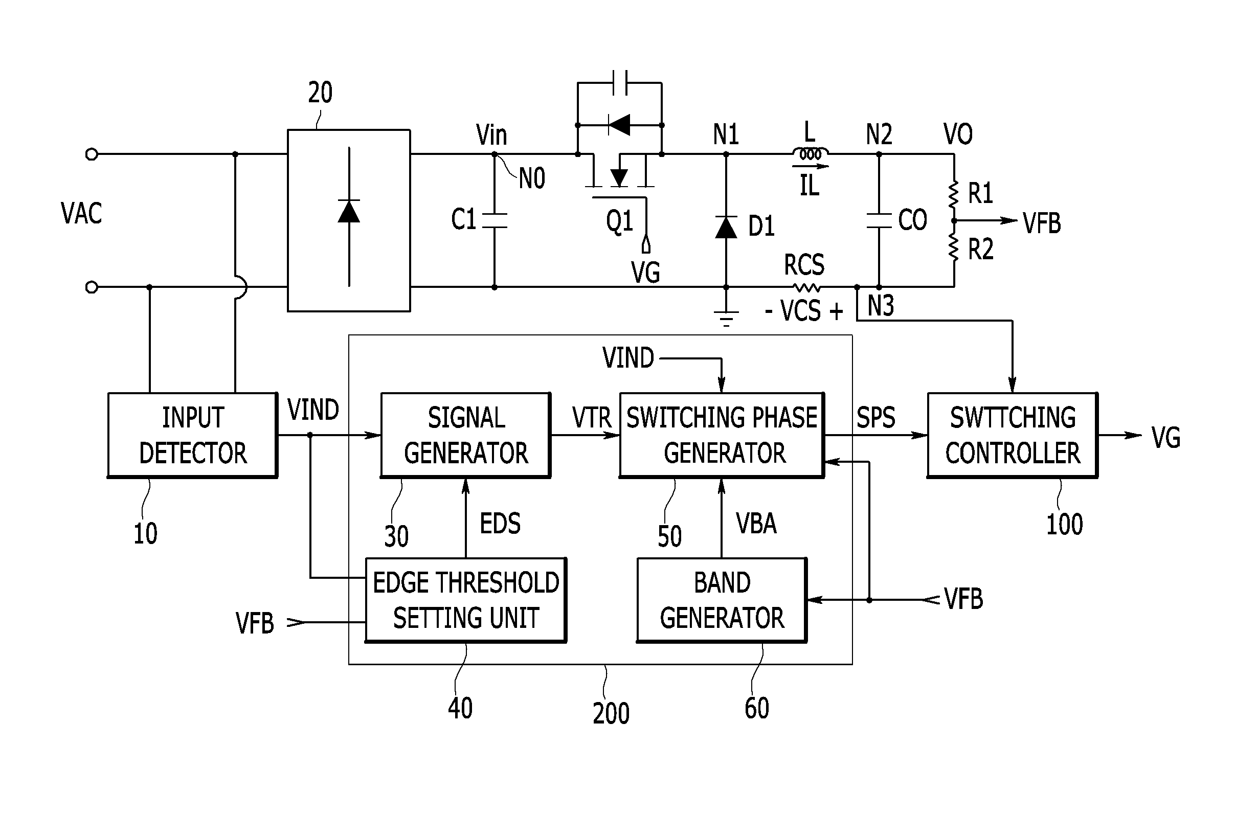
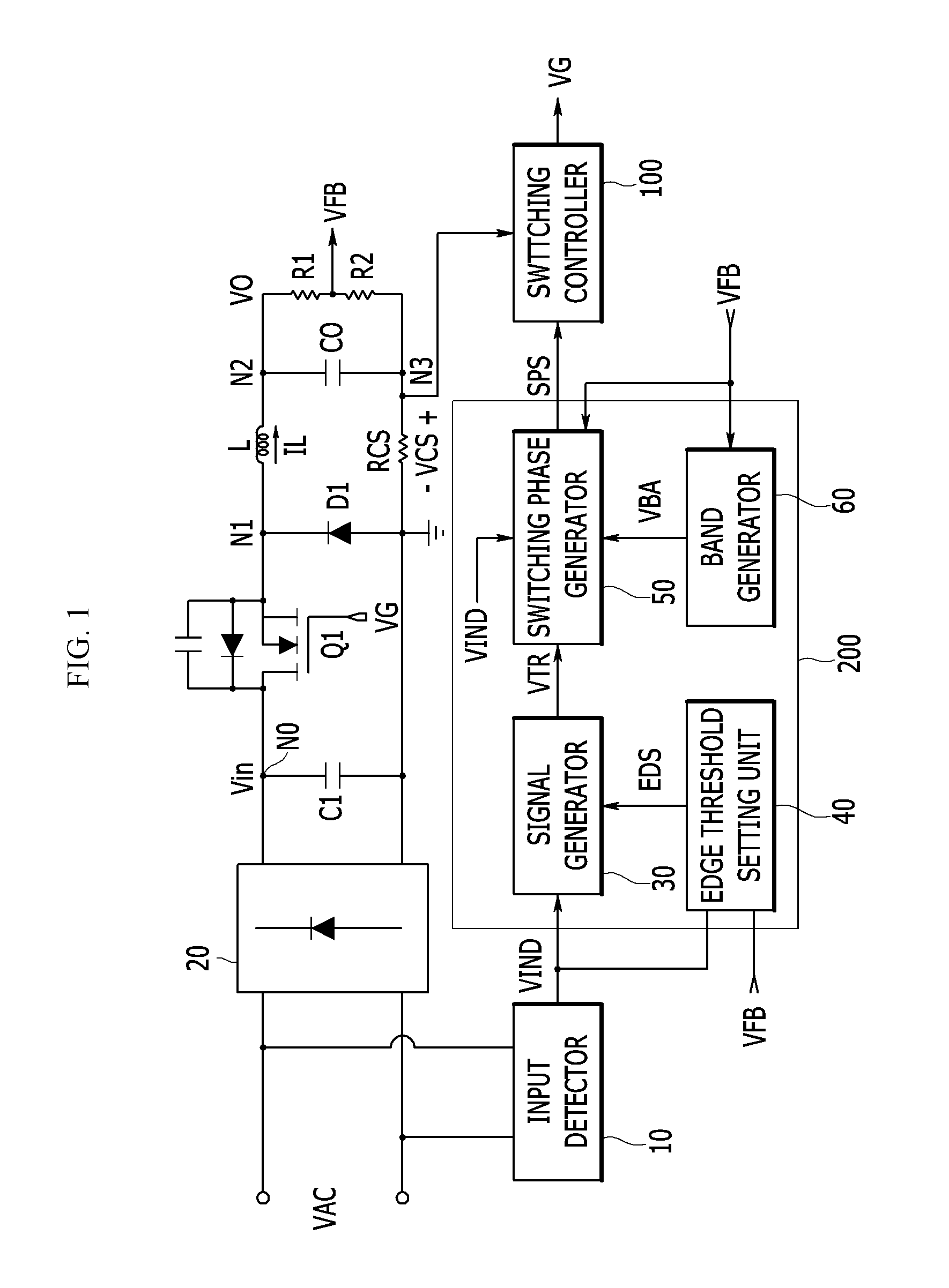
[0039]A burst mode control circuit according to an embodiment of the present i...


PUM


Abstract

Provided is a buck converter. The converter includes a power switch configured to receive and switch an input voltage and convert the input voltage into an output voltage, and a switch control circuit configured to generate a signal having a frequency synchronized with the input voltage, compensate for the signal by using an edge threshold voltage in an edge area of the signal according to at least one of a load state and the input voltage, and control switching of the power switch by using a result of comparing the signal with a band voltage corresponding to the output.

Description

CROSS-REFERENCE TO RELATED APPLICATIONS[0001]This application claims priority from U.S. Provisional Application No. 62 / 185,834, filed on Jun. 29, 2015 with the United States Patent and Trademark Office, the entire contents of which are incorporated herein by reference.BACKGROUND[0002](a) Technical Field[0003]Embodiments of the present invention relate to a switch control circuit including a burst mode control circuit and a converter including the switch control circuit.[0004](b) Description of the Related Art[0005]When a power switch of a converter switches during one cycle of an alternating current (AC) input which is input to the converter, a switching loss may be increased. For example, switching in a period in which the AC input is a high voltage increases the switching loss.[0006]Switching may occur only in a predetermined period in one cycle of the AC input according to a required load. For example, under a light load condition, switching may occur only in a predetermined peri...

Claims


Application Information

Patent Timeline
IPC IPC(8): H02M3/156H02M1/08
CPCH02M3/156H02M2001/0009H02M1/08H02M7/217G01R19/04Y02B70/10G01R19/175H02M1/083H02M1/0009H02M1/0003H02M1/0022H02M1/0025H02M1/0048H02M1/0054H02M1/0058H02M1/36H02M3/158H02M1/44
Inventor JIN, CHENGHAOMOON, SANGCHEOLCHUNG, BONGGEUNKOO, GWANBON
Owner SEMICON COMPONENTS IND LLC
Features
  • R&D
  • Intellectual Property
  • Life Sciences
  • Materials
  • Tech Scout
  • Unparalleled Data Quality
  • Higher Quality Content
  • 60% Fewer Hallucinations
Learn More